Check patentability & draft patents in minutes with Patsnap Eureka AI!

Fluidized powder manifold quantitative distribution and stable injection system

A quantitative distribution and multi-branch technology, which is applied in the direction of block/powder supply/distribution, supply configuration, combustion method, etc., can solve the problems of increased injection pressure loss and energy loss, large distribution error, and difficult distribution accuracy, etc. , to achieve the effect of increasing adjustment means and reducing dependence

Active Publication Date: 2018-09-14
HUATIAN NANJING ENG & TECH CORP MCC
View PDF5 Cites 0 Cited by
  • Summary
  • Abstract
  • Description
  • Claims
  • Application Information

AI Technical Summary

Problems solved by technology

But in fact, it is difficult to guarantee the distribution accuracy of pulverized coal distributors on the market. It is not easy for the distribution accuracy of each branch to reach 5%. Moreover, with the wear and tear of the distributor, its distribution error will become larger and larger, seriously affecting Uniform injection of pulverized coal
The equal length design of the branch pipes not only increases the length of the branch pipes (more than 70% increase in the amount of materials) and the difficulty of construction and maintenance, but also increases the resistance loss of each branch pipe with the increase of the branch pipe length, and the resulting blowing pressure loss and energy loss also increase. will increase
[0004] The above two factors have great restrictions on the quantitative distribution of fluidized powder, but this is not the most important thing. The most important thing is that the prior art lacks adjustment means for each branch pipe, and the injection volume of each branch pipe depends on the injection condition. Under the change, it can only change in the same trend (same increase or decrease), and it is difficult to meet the requirements of quantitative distribution and precise injection of each branch according to the set value

Method used


Image

  • Fluidized powder manifold quantitative distribution and stable injection system
  • Fluidized powder manifold quantitative distribution and stable injection system

Examples


Embodiment 1

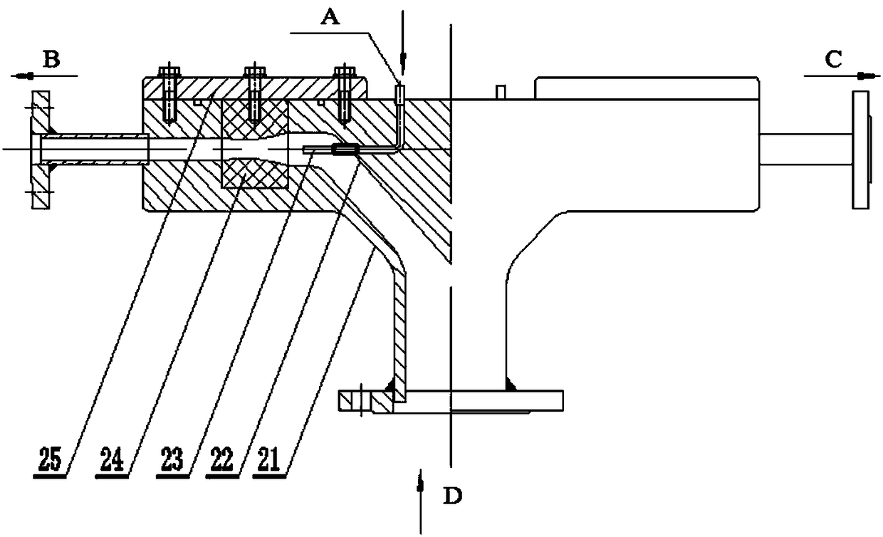
[0023] Such as Figure 1-2 As shown, the fluidized state powder manifold quantitative distribution and stable injection system of this embodiment includes a quantitative distribution mechanism 2; the quantitative distribution mechanism 2 includes a distribution body 21, a distribution cone 22 arranged in the distribution body 21, Several ejection gas nozzles 23 and several distribution rings 24 connected with the distribution cone 22;

[0024] The distribution body 21 includes a conical shell, a powder inlet communicating with the apex of the conical shell, and several powder outlets arranged along the circumferential direction on the side wall of the conical shell;

[0025] The bottom surface of the distribution cone 22 is connected to the top wall of the conical housing, the distribution cone 22 is coaxially arranged with the conical housing, and the conical surface of the distribution cone 22 is connected to the conical housing. The inner surface of the side wall is arrang...

Embodiment 2

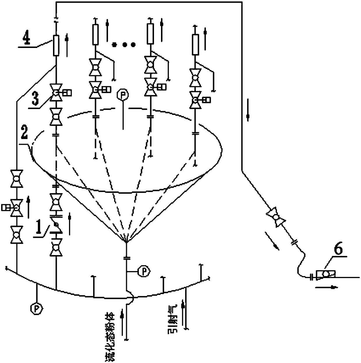
[0031] On the basis of the above-mentioned embodiments, the quantitative distribution mechanism 2 also includes an injection branch pipe communicated with the injection gas nozzle 23 and a blowing branch pipe communicated with the powder outlet; the injection branch pipe is provided with A flow regulating valve 1, a branch blowing valve 3 and a branch flow meter 4 are sequentially arranged on the spray branch pipe along the powder flow direction.

[0032] By changing the ejection air flow rate, the powder flow rate entering each branch pipe can be controlled, so that the distribution of powder materials in each branch pipe is in a controllable and adjustable state, avoiding the "blind spray" phenomenon, due to the introduction of ejection air in the distribution device , which reduces the dependence of the uniformity index on the accuracy of the equipment during the injection process, cancels the equal-length design of the distribution branch pipe, and increases the adjustment ...

Embodiment 3

[0034] On the basis of the above embodiments, several ejection gas channels are arranged in the distribution cone 22, and the ejection gas nozzle 23 is connected to the ejection gas channels through threads. The injection gas nozzle 23 is made of wear-resistant material.

[0035] The nozzle 23 and the distribution cone 22 are connected by pipe threads. The distance from the nozzle 23 to the distribution ring 24 can be adjusted by adjusting the length of the threaded section screwed into the distribution cone 22. Effect of fluidized powder. The nozzle 23 is made of wear-resistant material, which can prolong the service life of the nozzle 23, and the threaded connection can quickly replace the nozzle 23, reducing the time for overhauling the quantitative distribution mechanism 2.


PUM


Abstract

The invention discloses a fluidized powder multi-branch quantitative distribution and stable blowing system. The fluidized powder multi-branch quantitative distribution and stable blowing system is provided aiming at the problem that a blowing system in the prior art fails to realize quantitative control of each branch. The system comprises a quantitative distribution mechanism which comprises a distribution body, a distribution cone, a plurality of ejector nozzles and distribution rings. The distribution body comprises a conical shell, a powder inlet and a plurality of powder outlets, the bottom of the distribution cone is connected with the top wall of the conical shell, the distribution cone and the conical shell are in axially spaced arrangement, the distribution rings are matched with distribution grooves respectively, and powder passages are formed at positions, corresponding to powder outlet through holes, of the distribution rings. Each powder passage comprises a contraction section and an expansion section, a large-diameter end of each contraction section faces a corresponding inner powder outlet through hole, and a large-diameter end of each expansion section faces a corresponding outer powder outlet through hole. The ejector nozzles and the powder outlets are in coaxial arrangement. The fluidized powder multi-branch quantitative distribution and stable blowing system is effective in quantitative powder distribution for blowing branches.

Description

technical field [0001] The invention relates to a fluidized state powder multi-branch pipe quantitative distribution and stable injection system. Background technique [0002] In the process of distribution and injection of various powder materials such as coal powder, mineral powder, etc. in a single main pipe plus multiple branch pipes, it is very important to ensure the uniform distribution of materials on the branch pipes. For example, in the process of coal injection in blast furnaces, especially large and medium-sized blast furnaces, the inconsistency in the amount of pulverized coal injection at each tuyere will lead to temperature differences in the circumferential direction of the hearth, which will have an adverse effect on the "direct movement" of the blast furnace. In the coal injection process of the lime kiln, if the adjustment and control of the pulverized coal flow is unstable, and the distribution of the pulverized coal flow in each branch pipe is uneven, th...

Claims


Application Information

Patent Timeline
Patent Type & Authority Patents(China)
IPC IPC(8): F23K3/02
CPCF23K3/02F23K2203/008
Inventor 肖红涛周飞
Owner HUATIAN NANJING ENG & TECH CORP MCC
Features
  • R&D
  • Intellectual Property
  • Life Sciences
  • Materials
  • Tech Scout
  • Unparalleled Data Quality
  • Higher Quality Content
  • 60% Fewer Hallucinations
Learn More