Condenser pipe bundle

A condenser and steam technology, applied in steam/steam condensers, lighting and heating equipment, etc., can solve the problems of low volume ratio of tube bundles, steam channeling, large shell space, etc., and achieve large volume ratio of tube bundles and layout Compactness and the effect of reducing vapor resistance

Active Publication Date: 2016-07-06
SHANGHAI UNIVERSITY OF ELECTRIC POWER +1
View PDF7 Cites 4 Cited by
  • Summary
  • Abstract
  • Description
  • Claims
  • Application Information

AI Technical Summary

Problems solved by technology

However, the narrow-band downstream condenser tube bundle still has the disadvantages of low volume ratio of the tube bundle and the need for a large shell space, which has certain limitations in engineering applications, especially when the aspect ratio of the condenser shell is large (that is, the shell is long and narrow), the arrangement of two narrow-band downstream main condensation zones is a bit tight in space, and even makes the main steam channel too narrow, causing the steam flow rate in the main steam channel to exceed the reasonable flow rate of 80m / s. Excessive channeling of steam to the lower part of the tube bundle area, resulting in uneven steam load distribution

Method used


Image

  • Condenser pipe bundle
  • Condenser pipe bundle
  • Condenser pipe bundle

Examples


Embodiment 1

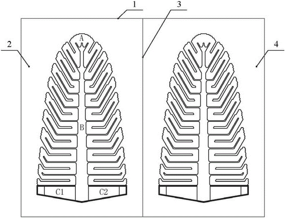
[0036] A cooling water single-tube-pass structure condenser is formed by using two tube bundles disclosed in the application in a left-right symmetrical arrangement, such as figure 1 As shown, the periphery of the left module tube bundle and the left side of the condenser shell 1 form the left main steam channel 2, and the middle main steam channel 3 is formed between the two tube bundle modules, and the periphery of the right module tube bundle and the right side of the condenser shell The side forms the main steam channel 4 on the right. The setting of the width of the main steam channel should be based on the fact that the flow velocity of the steam in this place is 70-90m / s. If the width of the main steam channel is too large or too small, the steam flow field will be unreasonable, resulting in a decrease in heat exchange or a decrease in steam resistance. Increase.

[0037] exist figure 1 In the above, taking the tube bundle on the left as an example, the tube bundle is...

Embodiment 2

[0048] The similarities between this embodiment and the first embodiment will not be described, and only the differences will be described.

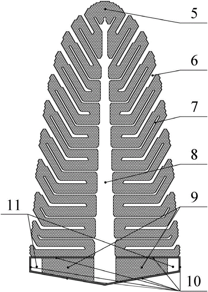
[0049] In this embodiment, the tube bundle is a cooling water double-tube structure with upper and lower halves, such as Figure 6 As shown, the middle part of the tube bundle is provided with an L-shaped split-pass steam baffle 12 .

Embodiment 3

[0051] The similarities between this embodiment and the first embodiment will not be described, and only the differences will be described.

[0052] Such as Figure 7 As shown, the tube bundle part of the condenser in this embodiment is composed of four tube bundles according to the present invention, and the tube bundles are all cooling water single-pass structures.


PUM


Abstract

The invention relates to a condenser pipe bundle. The condenser pipe bundle comprises a pine-tree-shaped main congealing area formed by arranging cooling water pipes in a crossed manner and right trapezoid air cooling areas. A vertical main channel used for gathering non-congealing gas is arranged inside the main congealing area, and the two air cooling areas are located below the main congealing area, distributed on the two sides of the vertical main channel and communicated with an extending section of the vertical main channel; and the air cooling areas and the main congealing area are separated through vapor blocking plates. Compared with the prior art, the main congealing area is distributed around the simple-shape vertical main channel used for gathering the non-congealing gas, the flow of the vertical main channel used for gathering the non-congealing gas is short, the non-congealing gas can flow into the air cooling areas after being gathered to the lower portion, and vapor locking of the main congealing area is reduced. In addition, the right trapezoid shape facilitates condensation of vapor in the air cooling areas; and the air cooling areas are symmetrically arranged on the two sides of the lower face of the main congealing area, the air cooling areas and the main congealing area are natural, the layout is compact, and the volume fraction of the pipe bundle is large.

Description

technical field [0001] The invention relates to a condenser tube bundle, in particular to a condenser tube bundle with an air-cooling zone located on both sides of the bottom of the tube bundle. Background technique [0002] The condenser is an important part of the power plant unit, responsible for the task of condensing the exhaust steam discharged from the steam turbine into water and establishing and maintaining a certain vacuum value at the steam exhaust port of the steam turbine. The design of the power station condenser is divided into two stages: thermal design and pipe layout design. If the layout of the condenser tube bundle in the later stage is reasonable, the performance of the condenser designed according to the HEI standard in the thermal design stage can be improved to varying degrees. If it is unreasonable , and even reduce the performance of the condenser designed according to the HEI standard. Therefore, the reasonable tube bundle arrangement of the conde...

Claims


Application Information

Patent Timeline
Patent Type & Authority Applications(China)
IPC IPC(8): F28B1/06F28B9/08
CPCF28B1/06F28B9/08
Inventor 张莉何坚忍姚秀平程浩然杨蒋文
Owner SHANGHAI UNIVERSITY OF ELECTRIC POWER
Why Eureka
Try Eureka