Method for reducing MIMO imaging radar near-field grating lobes

An imaging radar and grating lobe technology, which is applied in the field of MIMO radar, can solve problems such as the inability to optimize the design and can not be used to guide the design of MIMO arrays, and achieve the effect of overcoming the problem of high grating lobes and improving imaging quality.

Active Publication Date: 2016-07-06
苏州理工雷科传感技术有限公司
View PDF5 Cites 11 Cited by
  • Summary
  • Abstract
  • Description
  • Claims
  • Application Information

AI Technical Summary

Problems solved by technology

Although this method can achieve the effect of suppressing grating lobes to a certain extent, the optimal grating lobe level that this method can achieve for the specified target is determined, and the optimal design cannot

Method used


Image

  • Method for reducing MIMO imaging radar near-field grating lobes
  • Method for reducing MIMO imaging radar near-field grating lobes
  • Method for reducing MIMO imaging radar near-field grating lobes

Examples


Embodiment Construction

[0023] The present invention will be described in detail below with reference to the accompanying drawings and examples.

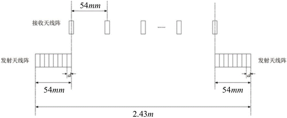
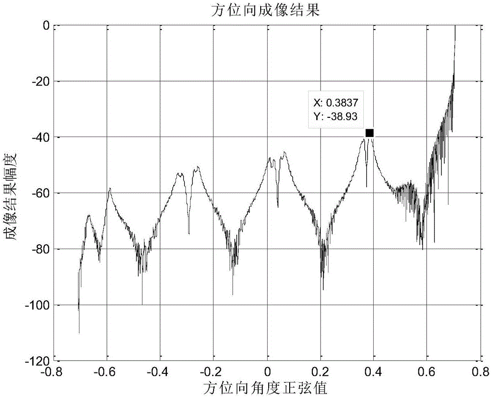
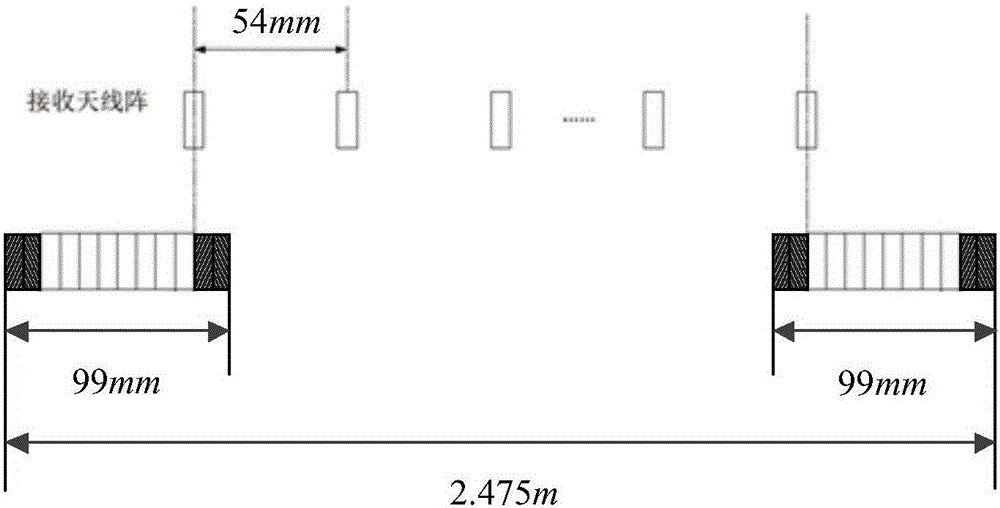
[0024] The invention provides a method for reducing near-field grating lobes of MIMO imaging radar. Aiming at the characteristic of near-field pattern having spatial variability, the MIMO array designed based on virtual array theory is optimized, and the transmitting array is extended at equal intervals and the transmitting Windowing is performed on the array. Firstly, the envelope sidelobe of the near-field pattern of the transmitting array is lowered as a whole, and then the grating lobes of the receiving array fall into the envelope sidelobe area of ​​the transmitting array, so that when the MIMO array is near-field imaging The grating lobe performance meets the index requirements.

[0025] It is assumed that the basic configuration adopted in MIMO array design is a dense array for transmitting and a sparse array for receiving, and the transmitting arra...


PUM


Abstract

The invention discloses a method for reducing MIMO imaging radar near-field grating lobes. Grating lobe performance of an MIMO array when near-field imaging is performed can achieve an index requirement through usage of the method. Aiming at the fact that a near-field directional diagram has a characteristic of spatial variability, optimization is performed on the MIMO array obtained through design based on a virtual array theory, an emitting array is prolonged in an equal interval manner, windowing processing is performed on the emitting array, envelope sidelobes of the near-field directional diagram of the emitting array are overall lowered firstly, and then grating lobes of a receiving array all fall into an envelope sidelobe region of the emitting array, so the grating lobe performance of the MIMO array when the near-field imaging is performed can achieve the index requirement, low grating lobe near-field imaging is achieved through adoption of the optimized MIMO array, and a certain degree of universality is possessed. Compared with an existing technology, the method can overcome a high grating lobe problem, resulted from near-field directional diagram distortions of the emitting and receiving arrays, of a synthetic directional diagram of the MIMO array, and the method improves the imaging quality of an MIMO radar for a near-field target.

Description

technical field [0001] The invention relates to the technical field of MIMO radar, in particular to a method for reducing near-field grating lobes of MIMO imaging radar. Background technique [0002] MIMO radar is a new radar system introduced in the radar field in recent years. It adopts a multi-antenna structure at both the transmitting end and the receiving end. Each transmitting antenna radiates mutually orthogonal signal waveforms at the same time, and each antenna at the receiving end receives all transmitted signals. And signal sorting is performed at the back end, thus obtaining observation channels and degrees of freedom far more than the actual number of receiving and transmitting array elements. The multi-observation channels that coexist in space enable the radar to collect echo information with different amplitudes, time delays or phases of the target in real time. This ability to obtain information from multiple channels in parallel is the fundamental advantage...

Claims


Application Information

Patent Timeline
IPC IPC(8): G01S13/89
CPCG01S13/89
Inventor 田卫明胡程王晶阳曾涛毛二可龙腾
Owner 苏州理工雷科传感技术有限公司
Why Eureka
Try Eureka