Intelligent remote wireless meter reading and billing system

A remote wireless and billing system technology, applied in the direction of signal transmission systems, instruments, etc., can solve problems such as communication blocking, affecting the accuracy of electric energy billing, real-time performance and reliability, and data loss, so as to ensure accuracy and timeliness stability, avoid data transmission conflicts, and provide management-level effects

Inactive Publication Date: 2016-07-06
RONGCHENG POWER SUPPLY CO STATE GRID SHANDONG ELECTRIC POWER CO
View PDF8 Cites 12 Cited by
  • Summary
  • Abstract
  • Description
  • Claims
  • Application Information

AI Technical Summary

Problems solved by technology

[0002] With the increasing demand for electricity in the society, the power supply network has spread to every corner of the city and the countryside, the number of power users is also increasing rapidly, and the number of electric meters is also increasing rapidly, which makes meter reading a heavy task. With the acceleration of the intelligent construction process of my country's power grid and the emergence of wireless sensor network technology, many medium-sized electric energy metering devices and remote meter reading and billing systems based on wireless sensor networks have appeared. The interaction is not friendly enough. On the other hand, due to the increase in the number of data acquisition devices and coordinators in the remote meter reading billing system, the collected and uploaded data continues to become huge, resulting in communication congestion and data loss, which greatly affects the power billing. Accuracy, Timeliness and Reliability

Method used


Image

  • Intelligent remote wireless meter reading and billing system
  • Intelligent remote wireless meter reading and billing system
  • Intelligent remote wireless meter reading and billing system

Examples


Embodiment Construction

[0017] The present invention will be further described below through specific embodiments and in conjunction with the accompanying drawings.

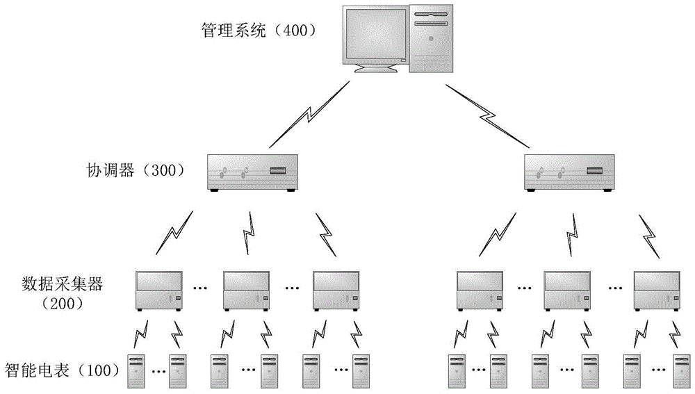
[0018] see figure 1 , is a structural principle block diagram of an intelligent remote wireless meter reading billing system of the present invention, the system includes: the system includes: at least one smart meter (100), at least one data collector (200), at least one coordinator (300 ), a management system (400), the data collector (200) connects and manages at least one smart meter (100), and the coordinator (300) connects and manages at least one data collector (200), the management system (400 ) to connect and manage at least one coordinator (300).

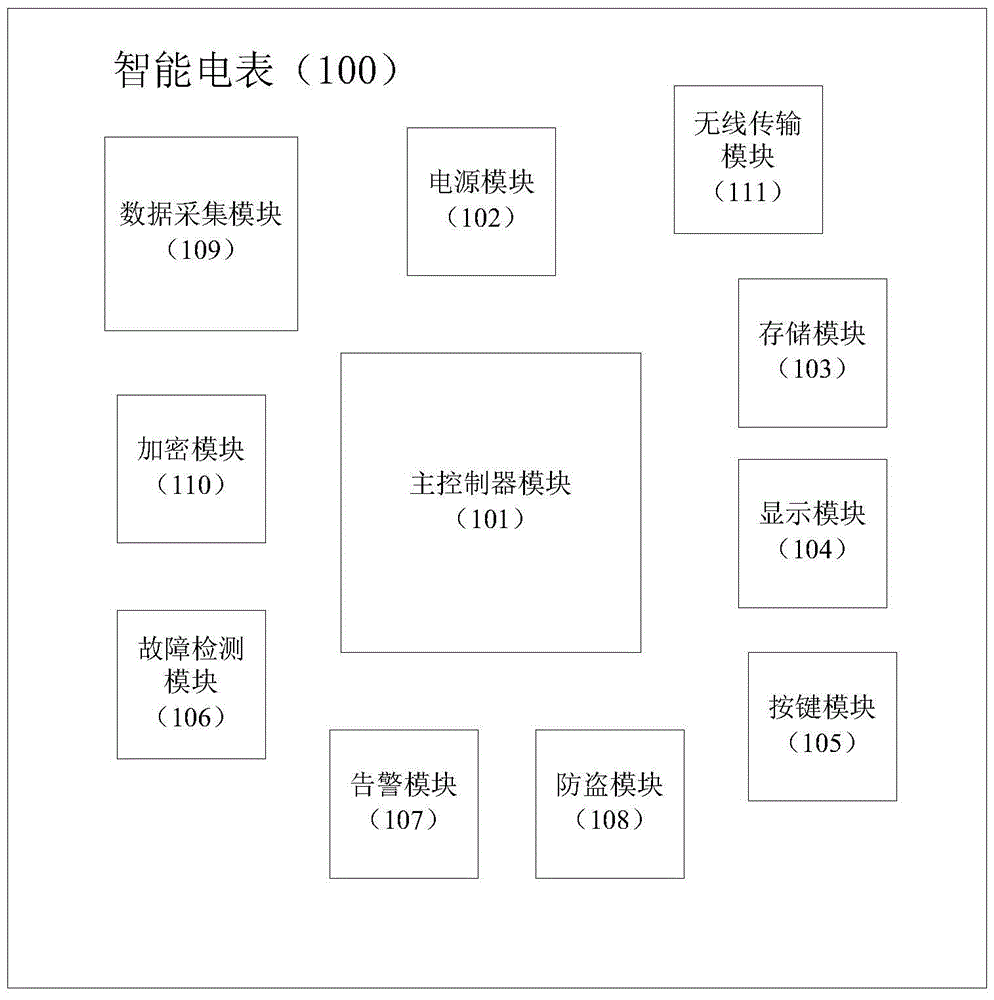
[0019] see figure 2, is a structural block diagram of the smart meter in the present invention, and the smart meter (100) includes: a main controller module (101), used for controlling each module of the smart meter; a power supply module (102), used for each module of the smart ...


PUM


Abstract

The invention provides an intelligent remote wireless meter reading and billing system which comprises an intelligent electric meter, a data acquisition unit, a coordinator and a management system.The coordinator creates a wireless network with independent network identification.The data acquisition unit joins the network.The intelligent electric meter encrypts power utilization information and generates a network address containing the data acquisition unit, identification information and a power utilization information frame of the encrypted power utilization information are uploaded to the data acquisition unit, the data acquisition unit detects the sub-channel state, if a sub-channel is in a busy state, the data acquisition unit enters a sending delay state and continues to carry out detection, and if the sub-channel is in an idle state, the data acquisition unit sends a data sending request to the coordinator and sends the power utilization information frame after receiving data sending allowing information returned by the coordinator.When the coordinator receives the power utilization frame and judges arrival of sending slot time, the coordinator sends the power utilization frame to the management system, the management system decrypts the power utilization information, displays the power utilization information in real time, calculates electric charge and sends short messages containing electric charge information to users.

Description

technical field [0001] The invention relates to the field of remote meter reading and charging, in particular to an intelligent remote wireless meter reading and charging system. Background technique [0002] With the increasing demand for electricity in the society, the power supply network has spread to every corner of the city and the countryside, the number of power users is also increasing rapidly, and the number of electric meters is also increasing rapidly, which makes meter reading a heavy task. With the acceleration of the intelligent construction process of my country's power grid and the emergence of wireless sensor network technology, many medium-sized electric energy metering devices and remote meter reading billing systems based on wireless sensor networks have appeared, but the current electric energy metering device design is relatively simple, man-machine The interaction is not friendly enough. On the other hand, due to the increase in the number of data acqui...

Claims


Application Information

Patent Timeline
Patent Type & Authority Applications(China)
IPC IPC(8): G08C17/02
CPCG08C17/02
Inventor 滕永慧盛智深郭建超董华平姜洪泽姜华刚连伟谭安强康瑞清姜为民
Owner RONGCHENG POWER SUPPLY CO STATE GRID SHANDONG ELECTRIC POWER CO
Why Eureka
Try Eureka