
A kind of microcavity oled device

A microcavity and device technology, which is applied in the field of microcavity OLED devices, can solve the problems affecting the viewing angle characteristics of the device, the color difference of the display effect of the OLED device, and the shift of the emission peak.

Active Publication Date: 2018-11-09
安徽中科春谷激光产业技术研究院有限公司
View PDF4 Cites 0 Cited by
  • Summary
  • Abstract
  • Description
  • Claims
  • Application Information

AI Technical Summary

Problems solved by technology

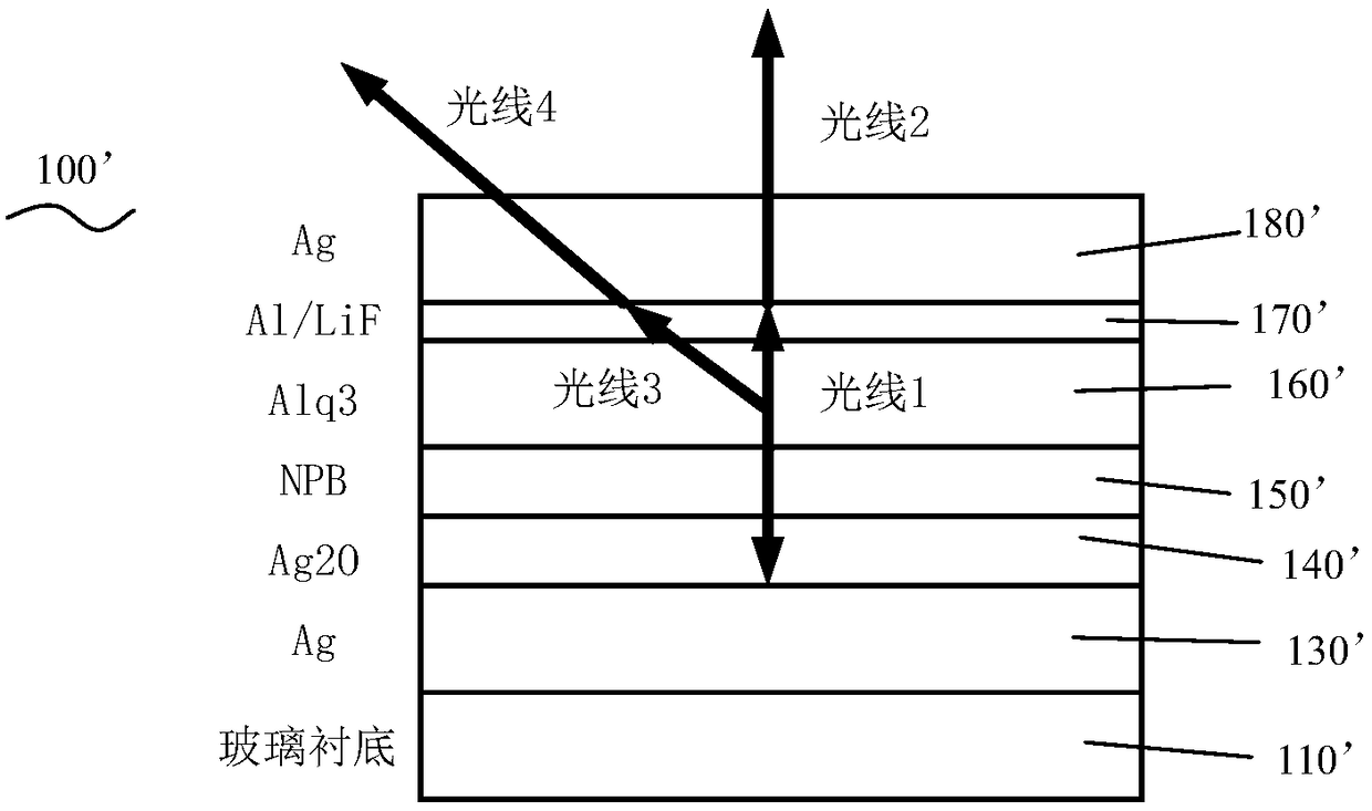
However, due to the wide-angle interference in the microcavity effect, the viewing angle characteristics of the device will be affected, that is, as the viewing angle shifts, the luminous peak will shift, resulting in chromatic aberration in the display effect of the OLED device.

Method used


Image

  • A kind of microcavity oled device
  • A kind of microcavity oled device
  • A kind of microcavity oled device

Examples


Embodiment Construction

[0026] In order to facilitate the understanding of the present invention, the present invention will be described more fully below with reference to the associated drawings. Preferred embodiments of the invention are shown in the accompanying drawings. However, the present invention can be embodied in many different forms and is not limited to the embodiments described herein. On the contrary, the purpose of providing these embodiments is to make the disclosure of the present invention more thorough and comprehensive.

[0027] Unless otherwise defined, all technical and scientific terms used herein have the same meaning as commonly understood by one of ordinary skill in the technical field of the invention. The terminology used herein in the description of the present invention is only for the purpose of describing specific embodiments, and is not intended to limit the present invention. As used herein, the term "and / or" includes any and all combinations of one or more of th...


PUM


Abstract

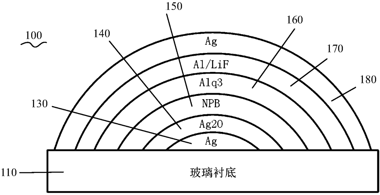
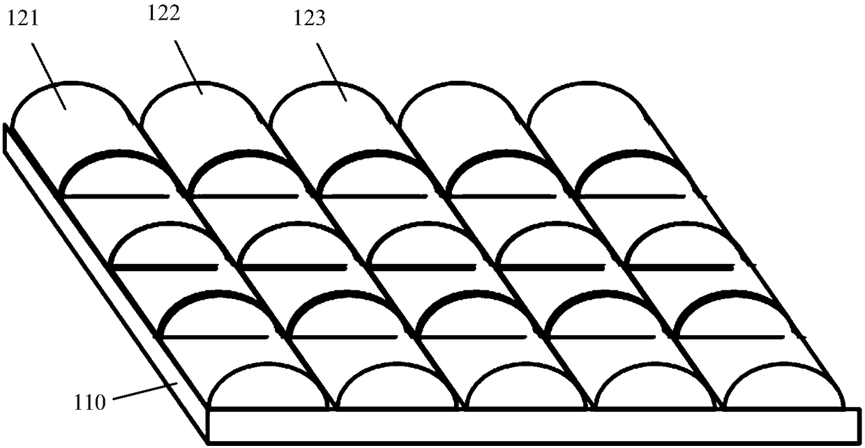
The present invention provides a microcavity OLED device, which includes a glass substrate and a plurality of pixels vertically distributed on the glass substrate, each of the pixels includes a plurality of sub-pixel microcavities, and each sub-pixel microcavity is The transverse cross-section has an arc-shaped structure that can make the path of the excited light in the sub-pixel microcavity at least partially consistent. In this way, the path of the excited light in the microcavity is the same, and the resulting resonance spectrum is also consistent, and there is no chromatic aberration or very small chromatic aberration from all angles, so that the problem of chromatic aberration can be improved.

Description

technical field [0001] The invention relates to the field of organic electroluminescence, in particular to a microcavity OLED device. Background technique [0002] Organic Light Emitting Diode (OLED) is a device that uses organic materials as the light-emitting layer under the action of an electric field. It is a new type of active light-emitting display device with light weight, thin thickness, high brightness, and viewing angle Wide, fast response, high luminous efficiency, no need for backlighting, and flexible display, etc., have important applications in the field of display and lighting, especially as the display device with the most potential to replace liquid crystal displays. According to the light-emitting position of the device, it can be divided into bottom emitting OLED (Bottom Emitting OLED, referred to as BEOLED) and top emitting OLED (TopEmitting OLED, referred to as TEOLED). [0003] The structure of the bottom-emitting OLED is that the OLED is fabricated o...

Claims


Application Information

Patent Timeline
Patent Type & Authority Patents(China)
IPC IPC(8): H01L51/50H01L51/52
CPCH10K50/00H10K50/80H10K50/85H10K50/86
Inventor 王欢
Owner 安徽中科春谷激光产业技术研究院有限公司
Learn More