
An alkaline dry battery electrolyte centrifugal absorption device

An absorption device and electrolyte technology, which is applied in the manufacture of primary battery equipment, battery pack components, circuits, etc., can solve the problems of high electrolyte absorption efficiency, insufficient electrolyte absorption, etc., and achieve not easy deterioration and good absorption effect. , to achieve the effect of absorption

Active Publication Date: 2018-09-25
ZHEJIANG YUNBANG BATTERY CO LTD
View PDF5 Cites 0 Cited by
  • Summary
  • Abstract
  • Description
  • Claims
  • Application Information

AI Technical Summary

Problems solved by technology

[0004] One of the purposes of the present invention is to address the shortcomings of the prior art, overcome the problem of insufficient electrolyte absorption under normal pressure, and provide a device that combines the injection and absorption processes of the electrolyte, and It is a centrifugal spray, and the absorption efficiency of the electrolyte is high

Method used

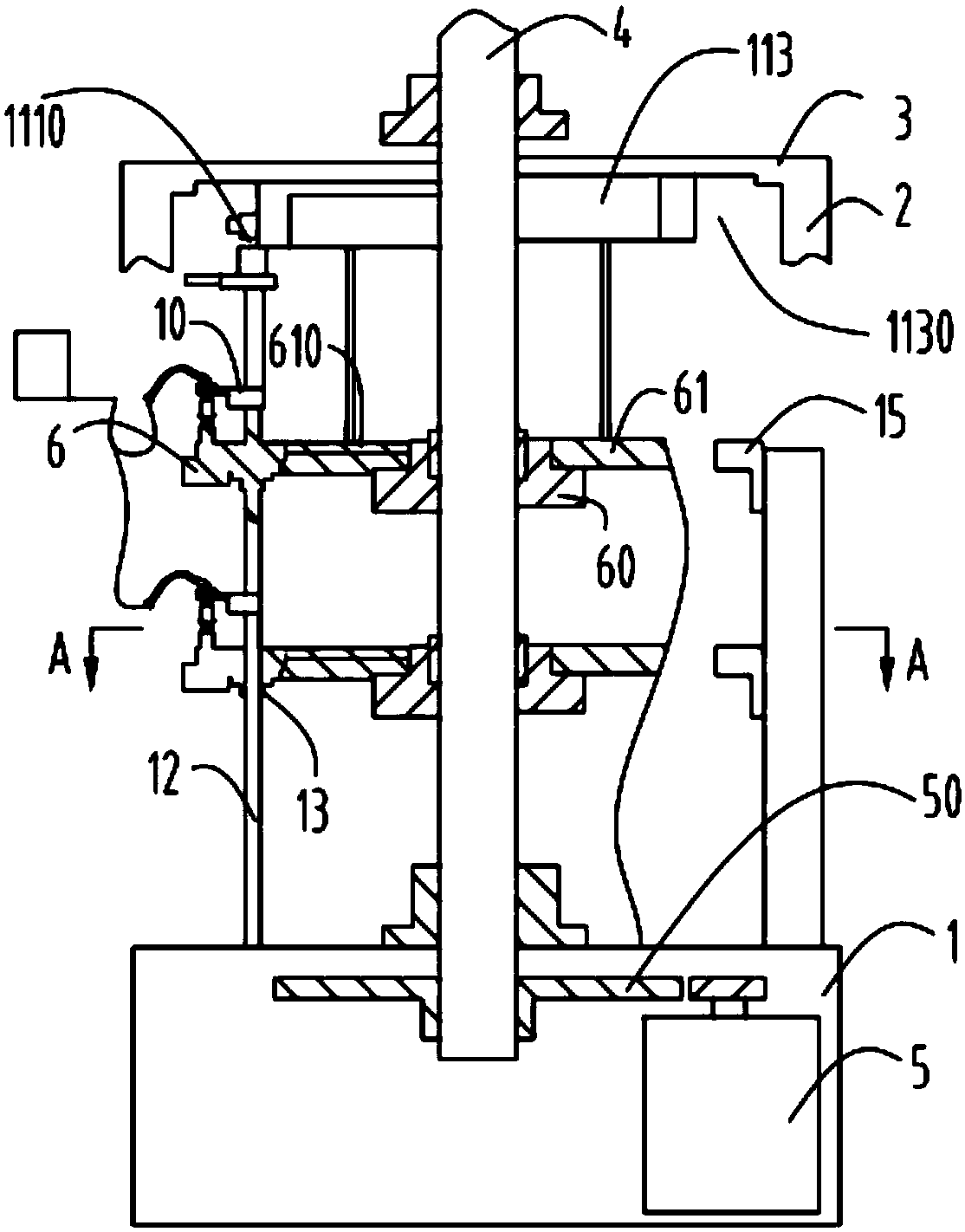

Image

  • An alkaline dry battery electrolyte centrifugal absorption device
  • An alkaline dry battery electrolyte centrifugal absorption device
  • An alkaline dry battery electrolyte centrifugal absorption device

Examples


Embodiment 1

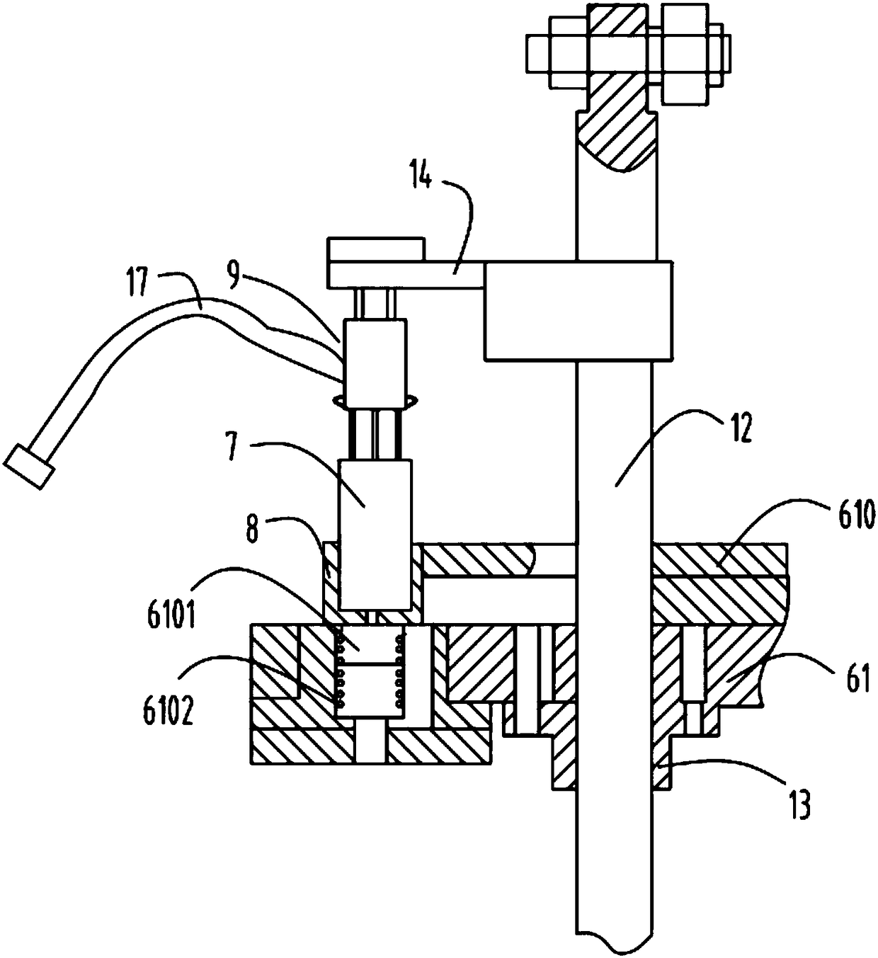
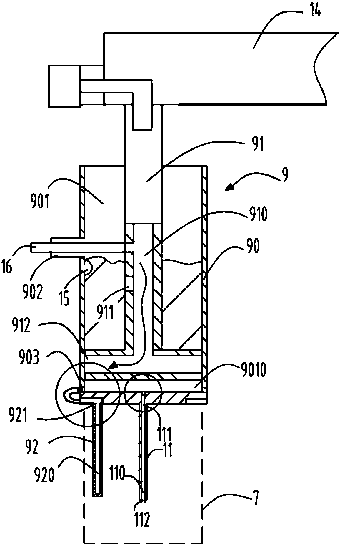
[0036] like figure 1 and figure 2As shown, an alkaline dry battery electrolyte centrifugal absorption device includes a base 1, a column 2 fixed to the base, a top plate 3 fixedly arranged on the top of the column, and a drive shaft 4 installed vertically on the base 1 and the top plate 3, The driving shaft 4 is powered by a gear 50 driven by the driving motor 5, and the driving shaft 4 is provided with a cup rotating mechanism 6, and the cup rotating mechanism 6 is evenly distributed along the circumferential direction with a plurality of cups 8 for installing batteries 7 It also includes an injection mechanism 9, which is used to inject the electrolyte into the battery 7; a lifting mechanism 10 that drives the injection mechanism 9 to move up and down, and the lifting mechanism 10 includes a first The cam 113 is provided with a cam spiral groove 1130 on the circumferential surface of the first cam 113, and the cam spiral groove 1130 is slidably connected with bearing conne...

Embodiment 2

[0060] In this embodiment, the number of the centrifugal guns 92 is two, the bottom plate 903 is provided with a groove 9030 for the centrifugal guns 92 to rotate and move, and also includes a centrifugal gun connecting rod 923 connecting the centrifugal guns 92 as a whole, The centrifugal gun connecting rod 923 is connected with a motor 924 , and the motor 924 drives the centrifugal gun 92 to move along the rotation movement slot 9040 . Except for this, other structures, positions and connections are the same as those in Embodiment 1.

[0061] During the working process, the electrolyte is thrown out under the action of centrifugal force to realize the injection of the electrolyte. The two centrifugal guns 92 rotate in the same direction through a motor 924. Centrifugation can realize the full throwing of the motor fluid, and realize dynamic spraying, which is beneficial to the absorption of the electrolyte.


PUM


Abstract

The invention relates to a centrifugal absorption device for alkaline dry battery electrolyte, comprising a base (1), a column (2) and a top plate (3); and an injection mechanism (9), which is used to make the battery (7) ) is under negative pressure, the electrolyte is injected into the battery (7); the electrolyte in the cavity (901) enters the liquid circulation channel (910) from the electrolyte inlet (911), and the injection rod (91) moves downward , the connection port (912) communicates with the liquid outlet (903) and the liquid inlet (921), and the electrolyte enters into the liquid channel (920); the centrifugal gun (92) is arranged on the bottom plate ( 9003), the electrolyte in it is thrown out by centrifugal force and injected into the battery (7). The problem of insufficient absorption of the electrolyte under normal pressure is overcome, and a device is provided, which combines the injection and absorption processes of the electrolyte, and is absorbed by rotating negative pressure, so that the absorption efficiency of the electrolyte is high.

Description

technical field [0001] The invention relates to the technical field of alkaline dry batteries, in particular to a centrifugal absorption device for alkaline dry battery electrolyte. Background technique [0002] Alkaline dry battery zinc injection glue and the injection mechanism in the electrolyte machine are the key components of the machine, which will directly affect the measurement accuracy and product performance of the electrolyte injection. The electrolyte injection mechanism of the alkaline dry battery in the prior art generally adopts The battery directly uses the cam mechanism to achieve the up and down movement during the filling process. The authorized notification number is the Chinese patent of CN100459231C, which discloses a vacuum absorbing device for alkaline dry battery electrolyte, which includes a base, a column and a top plate. The supporting cup rotation mechanism rotates synchronously in each layer, and each layer is evenly distributed with multiple ...

Claims


Application Information

Patent Timeline
Patent Type & Authority Patents(China)
IPC IPC(8): H01M2/36H01M50/60
CPCH01M6/005H01M50/60
Inventor 丁丞
Owner ZHEJIANG YUNBANG BATTERY CO LTD
Learn More