
Negative electrode flow field plate bionic structure capable of improving drainage performance of fuel cell

A cathode flow field and drainage performance technology, applied to fuel cell components, fuel cells, electrochemical generators, etc., can solve problems affecting fuel cell performance, "water flooding" and other issues

Inactive Publication Date: 2016-07-06
WUHAN UNIV OF TECH
View PDF8 Cites 11 Cited by
  • Summary
  • Abstract
  • Description
  • Claims
  • Application Information

AI Technical Summary

Problems solved by technology

[0002] The water management problem of fuel cells has always been the main factor that plagues its performance improvement, especially when the fuel cell stack is working at a high current density, it is prone to "water flooding" in the battery, which seriously affects the fuel cell. In this state, the water management problem in the battery stack becomes more serious, so it is necessary to use various methods to improve the water management problem in the fuel cell to improve the fuel performance, such as designing different flow field plate flow Although these methods have alleviated the degree of "flooding" in the battery to a certain extent, these methods are no longer applicable in the process of changing the working state of the battery, so other methods are sought More effective drainage measures become even more important

Method used


Image

  • Negative electrode flow field plate bionic structure capable of improving drainage performance of fuel cell
  • Negative electrode flow field plate bionic structure capable of improving drainage performance of fuel cell
  • Negative electrode flow field plate bionic structure capable of improving drainage performance of fuel cell

Examples


Embodiment Construction

[0026] The technical solutions of the present invention will be described below in conjunction with the accompanying drawings and embodiments.

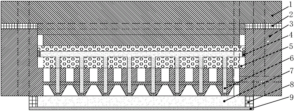
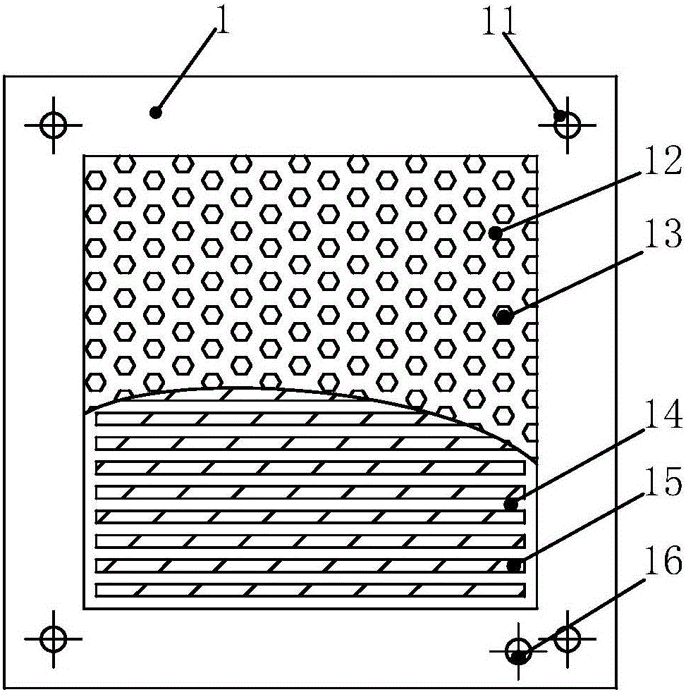
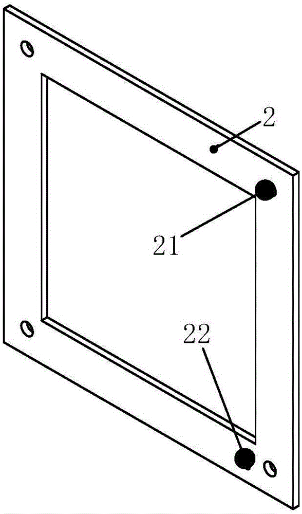
[0027] Such as figure 1 As shown, a cathode flow field plate bionic structure for improving fuel cell drainage performance according to the present invention includes an upper support layer 1, an outer gasket 2, a cathode flow field plate 3, an inner gasket 4, a lower support layer 5, and a liquid-absorbing material 6. Cathode gas diffusion layer 7, gasket 8 and cathode catalytic layer 9, the outer gasket 2 is arranged between the upper support layer 1 and the cathode flow field plate 3, and the inner gasket 4 is arranged between the cathode flow field plate 3 and the liquid-absorbing material 6 Between them, the cathode gas diffusion layer 7 is arranged between the liquid absorbing material 6 and the cathode catalytic layer 9 , and the gasket 8 is arranged between the cathode flow field plate 3 and the cathode catalytic layer 9 .

...


PUM


Abstract

The invention relates to the technical field of fuel cells, and specifically to a negative electrode flow field plate bionic structure capable of improving the drainage performance of a fuel cell. The bionic structure comprises an upper supporting layer, an outer gasket, a negative electrode flow field plate, an inner gasket, a lower supporting layer, a liquid-absorbing material, a negative electrode gas diffusion layer, a gasket and a negative electrode catalyst layer, wherein the outer gasket is arranged between the upper supporting layer and the negative electrode flow field plate; the inner gasket is arranged between the negative electrode flow field plate and the liquid-absorbing material; the negative electrode gas diffusion layer is arranged between the liquid-absorbing material and the negative electrode catalyst layer; and the gasket is arranged between the negative electrode flow field plate and the negative electrode catalyst layer. By adoption of the structure, the design of the bionic structure can better satisfy the bioengineering principle, so that the drainage speed of the fuel cell can be improved to a large extent; the bionic structure can be widely applied to fuel cells of multiple specifications; and a water-logging phenomenon in the fuel cell can be effectively prevented.

Description

technical field [0001] The invention relates to the technical field of fuel cells, in particular to a bionic structure of a cathode flow field plate for improving the drainage performance of a fuel cell. Background technique [0002] The water management problem of fuel cells has always been the main factor that plagues its performance improvement, especially when the fuel cell stack is working at a high current density, it is prone to "water flooding" in the battery, which seriously affects the fuel cell. In this state, the water management problem in the battery stack becomes more serious, so it is necessary to use various methods to improve the water management problem in the fuel cell to improve the fuel performance, such as designing different flow field plate flow Although these methods have alleviated the degree of "flooding" in the battery to a certain extent, these methods are no longer applicable in the process of changing the working state of the battery, so other...

Claims


Application Information

Patent Timeline
Patent Type & Authority Applications(China)
IPC IPC(8): H01M8/0202H01M8/023H01M8/0234
CPCH01M8/0202H01M8/023H01M8/0234Y02E60/50
Inventor 陈涛刘士华张恒陈见易伟
Owner WUHAN UNIV OF TECH
Learn More