
Power generator and mains supply automatic switching system

A technology for automatic switching and generators, which is applied to electrical components, circuit devices, emergency power arrangements, etc., and can solve problems such as large time intervals, affecting use, and potential safety hazards

Active Publication Date: 2016-07-06
LONCIN MOTOR
View PDF7 Cites 6 Cited by
  • Summary
  • Abstract
  • Description
  • Claims
  • Application Information

AI Technical Summary

Problems solved by technology

[0002] As a backup power supply, generators are widely used in modern production and life, such as industrial applications, high-rise elevator backup power, etc. In the prior art, the switch between the generator and the mains is usually manually started. When the mains fails, Then manually start the generator to work, and then stop the generator after the mains power supply is restored. This method is possible in general households and other occasions, but in industrial production, the above switching methods have relatively large time interval, which will cause serious efficiency loss or even safety hazards in industrial production. Although with the development of technology, people have gradually proposed automatic switching systems or devices, but the existing automatic switching technology has the following problems: poor stability, When the grid power supply is interrupted, the generator cannot accurately identify the start signal, and the generator cannot be reliably stopped after the grid restores power supply, which seriously affects the use

Method used


Image

  • Power generator and mains supply automatic switching system
  • Power generator and mains supply automatic switching system
  • Power generator and mains supply automatic switching system

Examples


Embodiment Construction

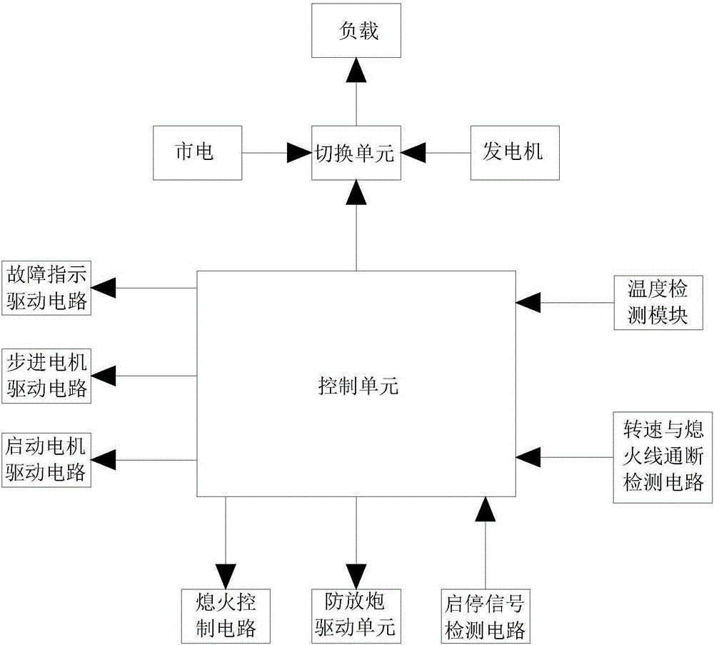
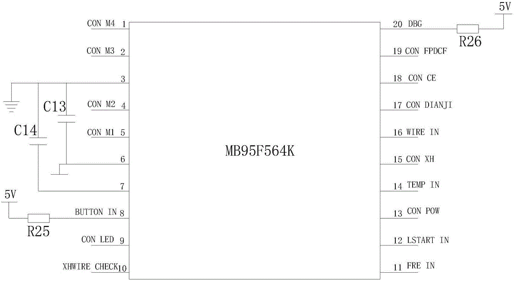
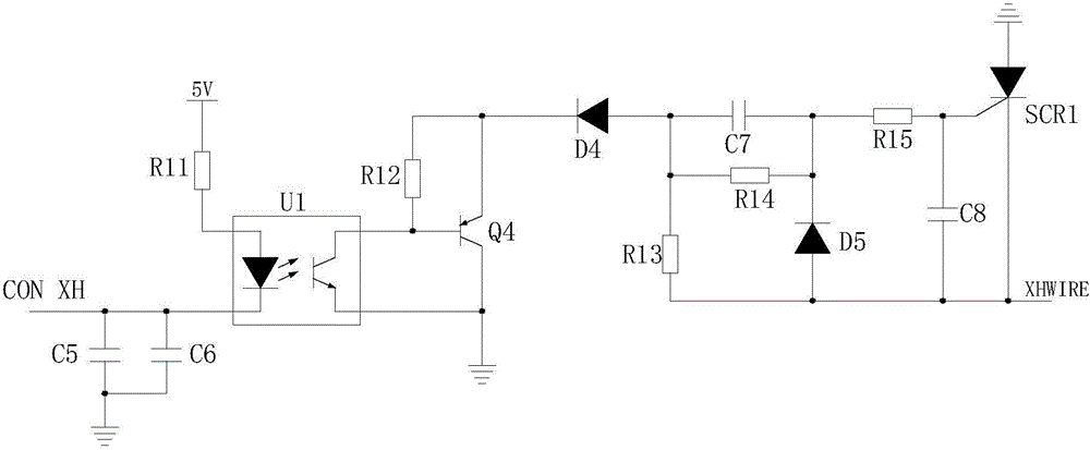
[0043] figure 1 For the schematic block diagram of the invention, figure 2 It is a structural schematic diagram of the control unit of the present invention, image 3 It is the schematic diagram of the flameout control circuit of the present invention, Figure 4 It is the schematic diagram of the starter motor driving circuit of the present invention, Figure 5 It is a schematic diagram of the rotating speed and flameout line on-off detection circuit of the present invention, Figure 6 It is the circuit schematic diagram of the power module of the present invention, Figure 7 It is the schematic diagram of the anti-blowout driving circuit of the present invention, Figure 8 It is a schematic diagram of the start-stop signal detection circuit of the present invention, Figure 9 It is a schematic diagram of the fault indication driving circuit of the present invention, Figure 10 It is a schematic diagram of the stepping motor drive circuit of the present invention, as sh...


PUM


Abstract

The invention provides a power generator and mains supply automatic switching system. The power generator and mains supply automatic switching system comprises a control unit, a power generator start-stop unit and a switching unit, wherein the control unit is used for acquiring a state signal of a mains supply whose power is supplied to a load, and outputting a control signal according to the state signal, the control signal comprises a power generator start-stop signal and a load power supply switching signal, the power generator start-stop unit is used for receiving the power generator start-stop signal output from the control unit to control a power generator to start or stop, the switching unit is used for receiving the load power supply switching signal output from the control unit and controlling a power supply path of the load to be switched between the mains supply and the power generator. Through the above structure, the switching between power supply by the power generator and power supply by the mains supply can be automatically completed when the power supply for a power grid is cut off or recovered, manual intervention is not needed, and the response time is short; and moreover, the power generator can be enabled to reliably start and stop during the switching process, and the system stably and reliably works.

Description

technical field [0001] The invention relates to a switching system, in particular to an automatic switching system between a generator and commercial power. Background technique [0002] As a backup power supply, generators are widely used in modern production and life, such as industrial applications, high-rise elevator backup power, etc. In the prior art, the switch between the generator and the mains is usually manually started. When the mains fails, Then manually start the generator to work, and then stop the generator after the mains power supply is restored. This method is possible in general households and other occasions, but in industrial production, the above switching methods have relatively large time interval, which will cause serious efficiency loss or even safety hazards in industrial production. Although with the development of technology, people have gradually proposed automatic switching systems or devices, but the existing automatic switching technology ha...

Claims


Application Information

Patent Timeline
Patent Type & Authority Applications(China)
IPC IPC(8): H02J9/06
CPCH02J9/066
Inventor 张勇隆郁邓勇刚杨继普尹利
Owner LONCIN MOTOR
Learn More