Rotor punching plate and permanent magnet motor

A technology of rotor punching and magnetic tiles, which is applied in the field of generators, can solve the problems of motor torque pulsation becoming larger and affecting motor noise, and achieve the effect of reducing torque pulsation and magnetic flux leakage

Active Publication Date: 2016-07-06
GREE ELECTRIC APPLIANCES INC +1
View PDF6 Cites 8 Cited by
  • Summary
  • Abstract
  • Description
  • Claims
  • Application Information

AI Technical Summary

Problems solved by technology

[0005] like figure 1 As shown, in the existing permanent magnet motor, the outer closed arc of the iron core 1' is circular, the shape of the magnetic tile groove 2' is rectangular, and the formed back electromotive force waveform is a trapezoidal wave, which contains many higher harmonics , leading to larger torque ripple of the motor and affecting the noise of the motor

Method used


Image

  • Rotor punching plate and permanent magnet motor
  • Rotor punching plate and permanent magnet motor
  • Rotor punching plate and permanent magnet motor

Examples


Embodiment 1

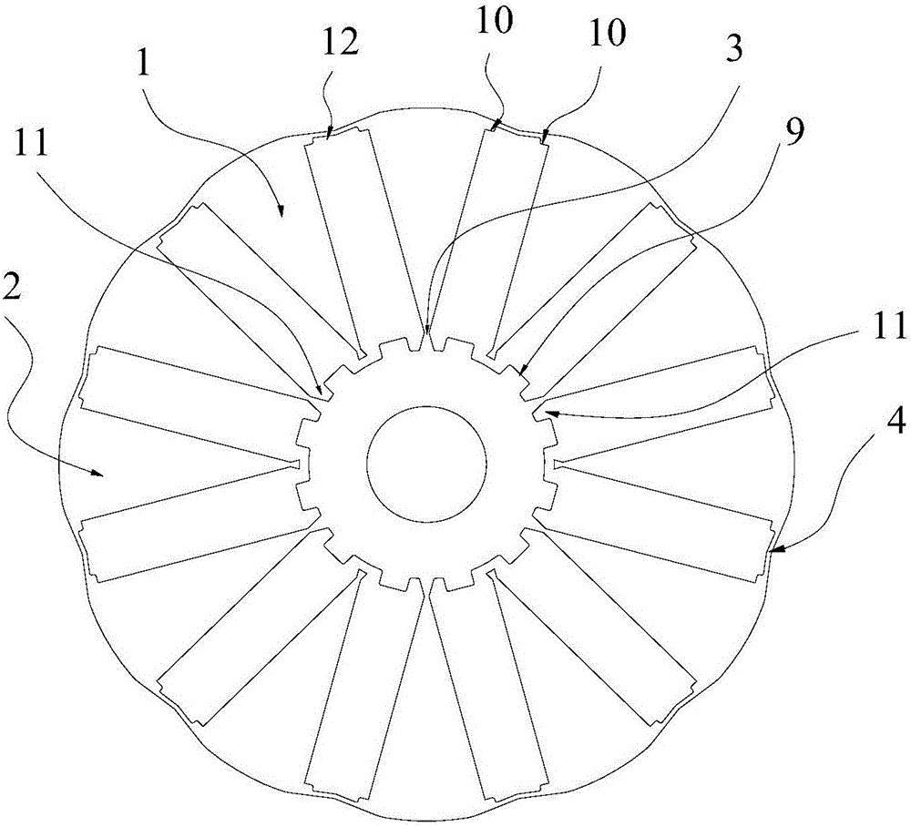
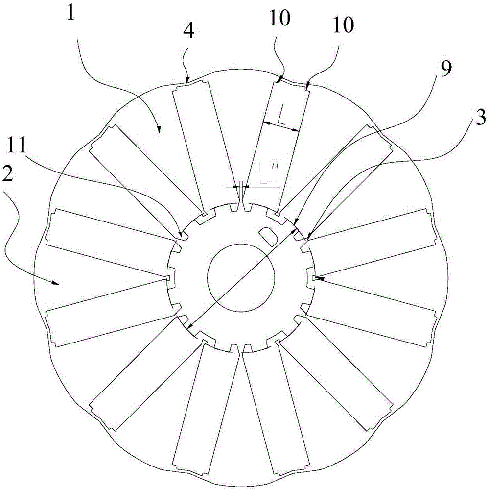
[0033] A rotor punch, such as Figure 2-3 As shown, it includes an iron core 1. A plurality of magnetic tile grooves 2 are evenly distributed along the circumference of the rotating shaft in the iron core 1. Each of the magnetic tile grooves 2 is arranged radially along the rotating shaft. Magnetic tiles are installed, and inner magnetic isolation bridges 3 are formed between adjacent magnetic tile grooves 2, and the inner magnetic isolation bridges 3 are disconnected from each other; a first positioning boss 9 is arranged on the inner side of the magnetic tile groove 2, Both sides of the first positioning boss 9 are respectively provided with inner air gaps 11; the outer side of the magnetic tile groove 2 is provided with two second positioning bosses 10, and the middle of the two second positioning bosses 10 An outer air gap 12 is provided. The optimal width of the magnetic tile groove 2 Among them, D is the minimum inner diameter of the inner side of the magnetic tile sl...

Embodiment 2

[0040] Different from Example 1, as Figure 4 As shown, a thin bridge 5 is provided in the middle of the phase-to-phase magnetic tile groove 2, and the magnetic tile groove 2 provided with the thin bridge 5 is divided into two small magnetic tile grooves 6 of equal size along the radial direction of the rotating shaft; that is, any adjacent One of the two magnetic tile grooves 2 is provided with a thin bridge 5, and the other is not provided with a thin bridge 5. The setting of the thin bridge 5 is mainly to strengthen the strength of the rotor punch structure and the magnetic field stability of the rotor punch during operation.

[0041] like Figure 5 As shown, the structure of the thin bridge 5 is linear, which is convenient for processing and installing magnetic tiles. A small magnetic tile is placed in the small magnetic tile groove 6, and the width of the small magnetic tile is the same as that of the magnetic tile.

[0042] like Image 6 As shown, the thin bridge 5 ca...

Embodiment 3

[0044] The difference from Embodiments 1 and 2 is that in order to unify the size of the magnetic tiles and obtain better strength of the rotor plate, as Figure 7As shown, the middle part of the magnetic tile groove 2 without thin bridge 5 is provided with a thin bridge 5 disconnected in the middle, and the magnetic tile groove 2 is divided into two small magnetic tile grooves 6 of equal size along the radial direction of the rotating shaft. That is, any two adjacent magnetic tile grooves 2 are provided with a thin bridge 5, but only one of the two thin bridges 5 is disconnected, and the magnetic tile groove 2 is divided into two small magnetic tiles of equal size along the radial direction of the rotating shaft. Slot 6. The disconnected thin bridge 5 blocks the magnetic flux leakage circuit between the poles, greatly reducing the magnetic flux leakage phenomenon here.

[0045] like Figure 5 As shown, the structure of the thin bridge 5 is linear, which is convenient for pr...


PUM


Abstract

The invention relates to the technical field of generators, in particular to a rotor punching plate and a permanent magnet motor. The rotor punching plate comprises an iron core, wherein a plurality of magnetic shoe grooves are evenly distributed in the iron core along the circumferential direction of a rotating shaft; each magnetic shoe groove is formed along the radial direction of the rotating shaft; a magnetic shoe is arranged in each magnetic shoe groove; and inner-side magnetic isolation bridges are formed between the adjacent magnetic shoe grooves and are disconnected from one another. The invention further provides the permanent magnet motor. The permanent magnet motor comprises the rotor punching plate. The inner-side magnetic isolation bridges are disconnected from one another, so that leakage flux loops at the inner sides of the magnetic shoe grooves are blocked; and leakage flux is reduced. The optimal widths of the magnetic shoe grooves can be quickly and accurately given through the minimum inner diameters of the inner sides of the magnetic shoe grooves, the number of rotor pole pairs and the widths of the inner-side magnetic isolation bridges; and optimal configuration of the structural strength and the magnetic property is achieved. Through an iron core outer arc formed by N curves which comprise eccentric circular arcs and straight scrap edges connected with two sides of the eccentric circular arcs, the air-gap reluctance of the outer arc side of the rotor punching plate along the radial direction is changed; and sine wave counter electromotive force is achieved.

Description

technical field [0001] The invention relates to the technical field of generators, in particular to a rotor punch and a permanent magnet motor. Background technique [0002] In permanent magnet motors, in order to improve the performance of the motor, it is usually necessary to obtain higher magnetic properties. Due to the price limit of permanent magnet materials, under the limited structure, compared with surface-mounted and embedded radial rotors, built-in tangential rotors The rotor structure can effectively increase the magnetic flux area, improve the effective air gap flux, and then improve the performance of the motor. [0003] However, the embedded permanent magnet with a tangential structure has different degrees of magnetic flux leakage on the inner and outer sides of the radial direction. The above-mentioned magnetic flux leakage caused by a short circuit between poles will reduce the efficiency and stability of the motor; in order to reduce the magnetic flux leak...

Claims


Application Information

Patent Timeline
Patent Type & Authority Applications(China)
IPC IPC(8): H02K1/27
CPCH02K1/27H02K2201/03H02K2213/03
Inventor 高晓峰胡余生王周叶
Owner GREE ELECTRIC APPLIANCES INC
Why Eureka
Try Eureka