Spliced transformer radiator

A transformer, splicing technology, applied in the direction of transformer/inductor cooling, transformer/inductor parts, electrical components, etc., can solve the problem of low heat conduction efficiency and heat dissipation efficiency of heat pipe, low overall efficiency of radiator, and increase production. The difficulty of processing and other problems can reduce the probability of scrapping the fuel tank, improve the natural heat dissipation effect, and improve the scope of application.

Pending Publication Date: 2021-03-23
江苏恒屹变压器股份有限公司
View PDF0 Cites 0 Cited by
  • Summary
  • Abstract
  • Description
  • Claims
  • Application Information

AI Technical Summary

Problems solved by technology

[0004] The purpose of the present invention is to provide a spliced ​​transformer radiator to solve the problem that the existing radiators proposed in the above background technology are usually directly welded on the oil tank, so that there are many welding points between the radiator and the oil tank. If there is a problem, it is easy to cause the transformer to be completely scrapped, which greatly increases the difficulty of production and processing. The existing radiator only relies on the steel heat dissipation pipe to contact the air for heat dissipation, but the heat conduction efficiency and heat dissipation efficiency of the steel heat dissipation pipe Both are not high, which leads to the problem that the overall efficiency of the radiator is not high, and it is not practical enough to use

Method used


Image

  • Spliced transformer radiator
  • Spliced transformer radiator
  • Spliced transformer radiator

Examples


Embodiment Construction

[0032] The following will clearly and completely describe the technical solutions in the embodiments of the present invention with reference to the accompanying drawings in the embodiments of the present invention. Obviously, the described embodiments are only some, not all, embodiments of the present invention. Based on the embodiments of the present invention, all other embodiments obtained by persons of ordinary skill in the art without making creative efforts belong to the protection scope of the present invention.

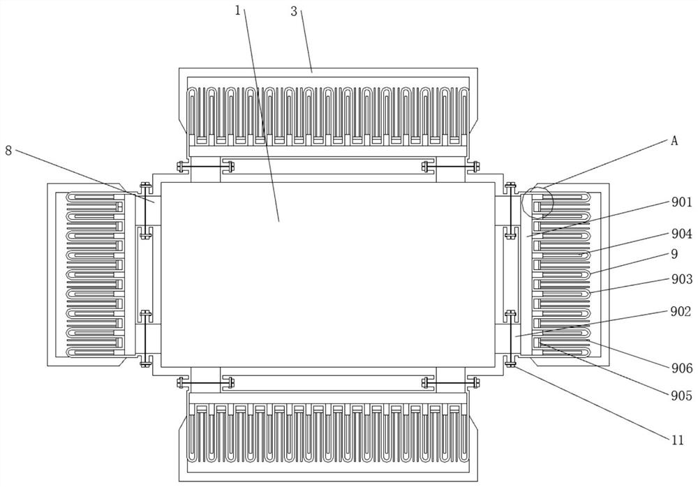
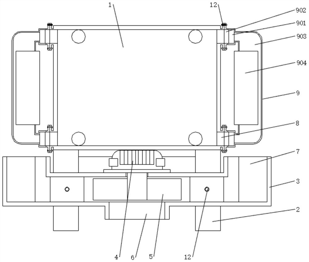
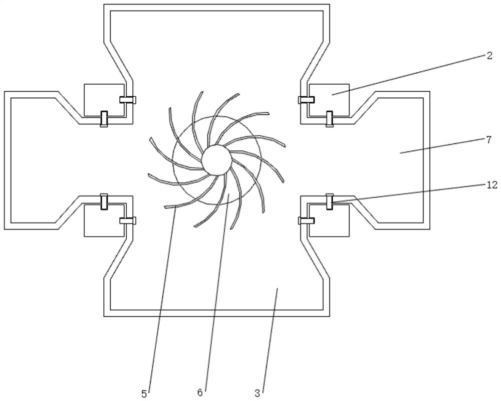
[0033] see Figure 1-8 , the present invention provides a technical solution: a spliced ​​transformer radiator, such as figure 1 , figure 2 and image 3 As shown, the bottom of the fuel tank 1 is welded and fixed with the leg 2, and the air guide box 3 fixedly installed on the leg 2 is arranged under the fuel tank 1, and the air guide box 3 or the water tank 1001 are fixedly installed on the leg 2 by bolts 12 , to facilitate quick installation and disassem...


PUM


Abstract

The invention discloses a spliced transformer radiator. Thespliced transformer radiator comprises an oil tank, a fixing pipe, an air cooling heat dissipation device and a water cooling heat dissipation device; supporting legs are fixedly welded to the bottom of the oil tank; an air guide box fixedly installed on the supporting legs is arranged below the oil tank; a driving motor is fixedly installed at the top of the air guide box; and the lower end of the driving motor penetrates through the air guide box to be connected with centrifugal fan blades; the centrifugal fan blades are suspended inthe air guide box; and an air inlet is formed in the bottom of the air guide box. According to the spliced transformer radiator, the centrifugal fan blades and the air guide box are adopted; the airguide box is installed below the oil tank; the driving motor drives the centrifugal fan blades to rotate; the centrifugal fan blades extract air through the air inlet and exhaust the air through an air outlet; airflow exhausted through the air outlet passes through the outer sides of radiating fins and takes away heat; when the centrifugal fan blades stop operating, natural wind is blown into gapsamong the radiating fins; and therefore, obstruction caused by the centrifugal fan blades is avoided, and the natural radiating effect of the radiator is improved.

Description

technical field [0001] The invention relates to the technical field of transformer radiators, in particular to a spliced ​​transformer radiator. Background technique [0002] Transformers will inevitably generate waste heat during operation, and in order to avoid insulation damage caused by the accumulation of waste heat, a radiator is required for heat dissipation. [0003] The existing radiator is usually directly welded on the fuel tank, so that there are many welding points between the radiator and the fuel tank. Once there is a problem in the welding process, it is very easy to cause the transformer to be completely scrapped, which greatly increases the difficulty of production and processing. Now Some radiators only rely on steel heat dissipation pipes to contact air for heat dissipation, but the heat conduction efficiency and heat dissipation efficiency of steel heat dissipation pipes are not high, which leads to the overall efficiency of the radiator is not high, it ...

Claims


Application Information

Patent Timeline
Patent Type & Authority Applications(China)
IPC IPC(8): H01F27/08H01F27/12H01F27/14H01F27/16H01F27/22
CPCH01F27/085H01F27/12H01F27/14H01F27/16H01F27/22
Inventor 刘兴慧
Owner 江苏恒屹变压器股份有限公司
Why Eureka
Try Eureka