Food stirring device

A technology of stirring device and food, which is applied to mixers with rotary stirring devices, accessories of mixers, transportation and packaging, etc., can solve the problems of inconvenience, uneven stirring of agitating bodies, unadjustable height of agitating bodies, etc., to prevent stirring Uneven, ensure full contact effect

Inactive Publication Date: 2016-07-13
慈溪市环球电器有限公司
View PDF5 Cites 5 Cited by
  • Summary
  • Abstract
  • Description
  • Claims
  • Application Information

AI Technical Summary

Problems solved by technology

[0002] The food mixer can quickly stir various foods. The function of the existing mixer is too single. Some solid foods need to be crushed first and then stirred, such as meat. At thi

Method used


Image

  • Food stirring device
  • Food stirring device
  • Food stirring device

Examples


Embodiment 1

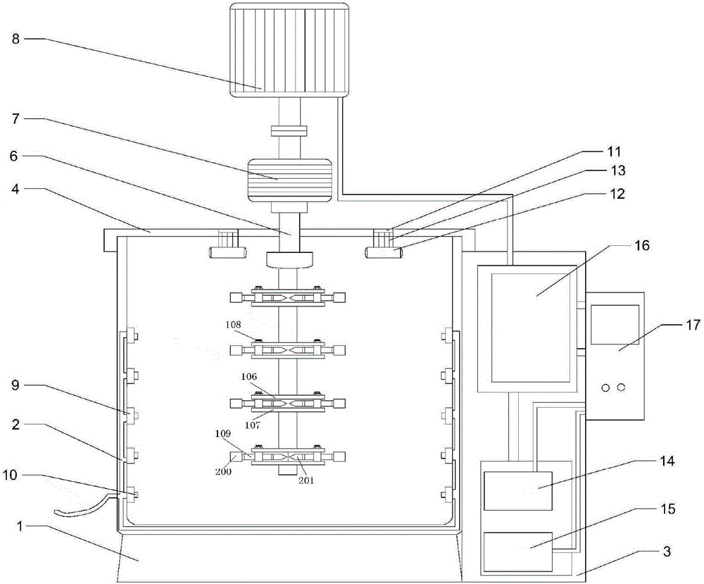
[0029] Such as figure 1 , 3 The present embodiment food mixing device comprises:

[0030] Base 1, mixing tank 2, stirring device and protection body 3, the mixing tank 2 is installed on the base 1, the protection body 3 is installed on the right side of the base 1, and the top of the mixing tank 2 is provided with a sealing cover 4 .

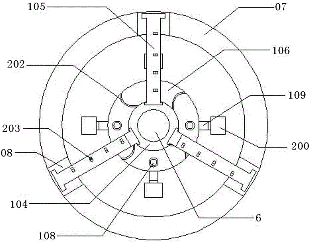
[0031] Described stirring device comprises stirring shaft 103, stirring shaft sleeve 104, stirring shaft support bar 105 and cutter fixed plate; The quantity is the same, and the number of the sliding groove 08 and the stirring shaft support rod 105 is three; one end of the stirring shaft support rod 105 is rotationally connected with the edge of the stirring shaft sleeve 14, and the other end is slidably connected in the sliding groove 08; the stirring shaft The sleeve 104 is rotatably connected with the upper end of the stirring shaft 103 .

[0032] The cutter fixed disk is evenly fixed on the stirring shaft 103, including an upper cutter ...

Embodiment 2

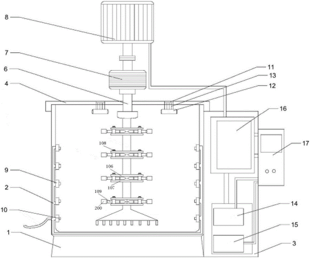
[0042] Such as figure 2 , 3 As shown, in the food stirring device of this embodiment, on the basis of Embodiment 1, in order to further enhance the stirring effect at the bottom of the stirring barrel, the bottom end of the stirring shaft is connected with a brush body.

Embodiment 3

[0044] Such as Figure 4 As shown, the food mixing device of this embodiment, on the basis of Embodiments 1 and 2, the rotating electrical machine is connected to a solar power generation device 22, and the solar power generation device 22 includes a butterfly condenser 23, a Stirling engine, and an automatic sunlight tracking device 24 and a generator 25, wherein the butterfly condenser 23 reflects, concentrates and directly heats the thermal chamber of the Stirling engine, and then utilizes the rotational motion generated by the Stirling engine to drive the generator 25 to rotate to realize power generation, and Utilize the automatic sunlight tracking device 24 to improve the solar energy receiving rate; the solar power generation device 22 is connected to the storage battery 29 through wires, and the storage battery 29 realizes the electric energy storage of the solar power generation part, and at the same time, starts the Stirling engine and the automatic sunlight tracking ...


PUM


Abstract

The invention discloses a food stirring device.The food stirring device comprises a base, a stirring bucket, a stirring device body, a protection body, a barrel-shaped inner shell and a barrel-shaped outer shell.The stirring bucket is installed on the base, the protection body is installed on the right side of the base, and a sealing cover is arranged at the top of the stirring bucket; the inner shell and the outer shell are matched and connected to form a cavity of the stirring bucket; a spraying head is arranged in the cavity, a through hole is formed in the inner shell along a spiral line, nozzles of the spraying head and the through hole are adapted, and the spraying head is communicated with compressed air outside the stirring bucket through a pipe; the stirring device body comprises a stirring shaft, a stirring shaft sleeve, stirring shaft supporting rods and cutter fixing discs; the stirring shaft sleeve is rotationally connected to the upper end of the stirring shaft; one ends of the stirring shaft supporting rods are rotationally connected with the edge of the stirring shaft sleeve, and the other ends of the stirring shaft supporting rods are connected into sliding grooves in a sliding mode; the stirring shaft sleeve is rotationally connected with the upper end of the stirring shaft.

Description

technical field [0001] The invention relates to a food stirring device. Background technique [0002] The food mixer can quickly stir various foods. The function of the existing mixer is too single. Some solid foods need to be crushed first and then stirred, such as meat. At this time, it needs to be manually crushed, which is very inconvenient. The height cannot be adjusted, and when there is too much mixture in the mixing barrel, the stirring body may stir unevenly. Contents of the invention [0003] In view of the above problems, the present invention provides a food stirring device with reasonable structure, uniform stirring and good stirring effect. [0004] In order to achieve the above object, the food stirring device of the present invention includes: [0005] A base, a mixing tank, a stirring device and a protection body, the mixing tank is installed on the base, the protection body is installed on the right side of the base, and the top of the mixing tank is pr...

Claims


Application Information

Patent Timeline
IPC IPC(8): B01F13/02B01F15/00B02C4/08B01F33/40
CPCB02C4/08B01F27/0722B01F27/118B01F33/05B01F33/408B01F33/402B01F33/4094B01F35/121B01F2101/06
Inventor 高洽伸
Owner 慈溪市环球电器有限公司
Why Eureka
Try Eureka