Automatic discharging device

A technology of automatic cutting and feeding mechanism, applied in metal processing and other directions, can solve the problems of high investment cost, waste generation, waste of manpower, etc.

Inactive Publication Date: 2016-07-13
CHONGQING DINGZU MACHINERY MFG
View PDF0 Cites 0 Cited by
  • Summary
  • Abstract
  • Description
  • Claims
  • Application Information

AI Technical Summary

Problems solved by technology

Such a cutting method is inefficient, and the degree of automation is low, which wastes manpower
In addition, it is easy to cause waste due to human negligence, which can

Method used


Image

  • Automatic discharging device
  • Automatic discharging device
  • Automatic discharging device

Examples


Embodiment Construction

[0027] The preferred embodiments of the present invention will be described in detail below with reference to the accompanying drawings.

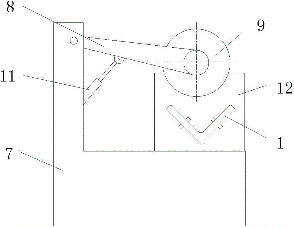
[0028] Such as figure 1 Shown is a schematic structural view of an embodiment of the automatic unloading device of the present invention. The automatic blanking device of this embodiment includes a blanking and cutting mechanism, a feeding mechanism cooperating with the blanking and cutting mechanism, and a blocking mechanism for positioning workpieces. Blanking cutting mechanism comprises frame 7, and the knife rest 8 that is installed on described frame 7 and the cutting tool 9 that is installed on described knife frame 8 are rotated, and frame 7 is provided with the motor that is used to drive cutting tool 9 rotations 10. An oil cylinder 11 for driving the tool post 8 to rotate is provided between the frame 7 and the tool post 8 .

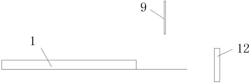
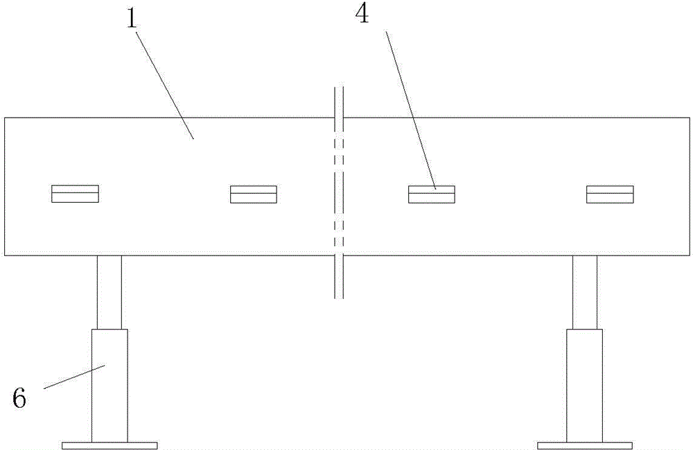
[0029] The feeding mechanism includes a V-shaped track body 1 arranged at the feeding end of the cutting...


PUM


Abstract

An automatic discharging device comprises a discharging cutting mechanism, a feeding mechanism and a stopping mechanism. The discharging cutting mechanism comprises a machine frame, a cutter holder and a cutter, wherein the cutter holder is installed on the machine frame in a rotating-fit mode, and the cutter is installed on the cutter holder. A motor for driving the cutter to rotate is arranged on the machine frame. An oil cylinder is arranged between the machine frame and the cutter holder. The feeding mechanism comprises a V-shaped track body arranged at the feeding end of the cutting mechanism. The two side walls of the V-shaped track body are each provided with rolling mechanisms at intervals. Each rolling mechanism comprises an installation hole formed in the side wall of the V-shaped track body. A rotating shaft is arranged inside each installation hole. A rolling body is arranged on each rotating shaft in a rotating-fit sleeving mode. The axis of each rotating shaft is perpendicular to intersection lines of the two side walls of the V-shaped track body. The stopping mechanism comprises a stopping plate arranged on the discharging side of the discharging cutting mechanism. The automatic discharging device further comprises a control system. The control system comprises a controller and a touch switch arranged on the stopping plate. A reversing electromagnetic valve is arranged on a gas path of the oil cylinder. A driving control circuit is arranged on the motor.

Description


Claims


Application Information

Patent Timeline
Owner CHONGQING DINGZU MACHINERY MFG
Why Eureka
Try Eureka