
Small sample dyeing bracket for filament/yarn laboratory

A laboratory and yarn technology, applied in the field of dyeing stents, can solve the problem that the inner filaments or yarns are difficult to dye and dye, the inner filaments or yarns are not easy to infiltrate and dye, and the filaments or yarns are entangled with each other. and other problems, to achieve the effect of leveling effect and mutual entanglement, reducing mutual entanglement and reducing friction.

Inactive Publication Date: 2016-07-13
ZHEJIANG TEXTILE & FASHION COLLEGE +1
View PDF5 Cites 2 Cited by
  • Summary
  • Abstract
  • Description
  • Claims
  • Application Information

AI Technical Summary

Problems solved by technology

[0002] There are usually two types of dyeing supports for filament or yarn laboratories: one is a flat support, which adjusts the length of filaments or yarns through slide rail screws, but when more filaments or yarns are wound , threading back and forth at the first and last two winding positions will cause the yarns to overlap and cover each other, which will increase the thickness of the wrapped yarns, which will easily cause the inner filaments or yarns to be difficult to be saturated and colored by the dye solution, resulting in color difference between the inner and outer layers , and easily entangled with each other
The other is a spring-type support, which adjusts the length of the filament or yarn by rotating the spring, but the stainless steel sheets are used as baffles on both sides of the top of the spring, and the thickness of the wound yarn increases to make the inner filament or yarn The problem that the yarn is not easy to be infiltrated and dyed by the dyeing solution, and it is easy to cause color difference between the inner and outer layers
Therefore, both of these commonly used solutions suffer from uneven dyeing and intertwining of filaments or yarns

Method used


Image

  • Small sample dyeing bracket for filament/yarn laboratory
  • Small sample dyeing bracket for filament/yarn laboratory
  • Small sample dyeing bracket for filament/yarn laboratory

Examples


Embodiment Construction

[0014] The present invention will be described in further detail below in conjunction with the accompanying drawings.

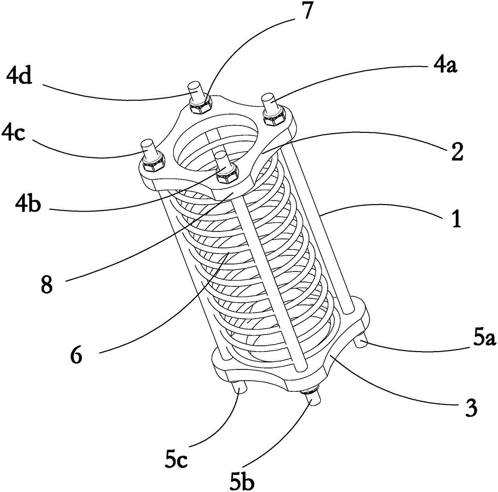
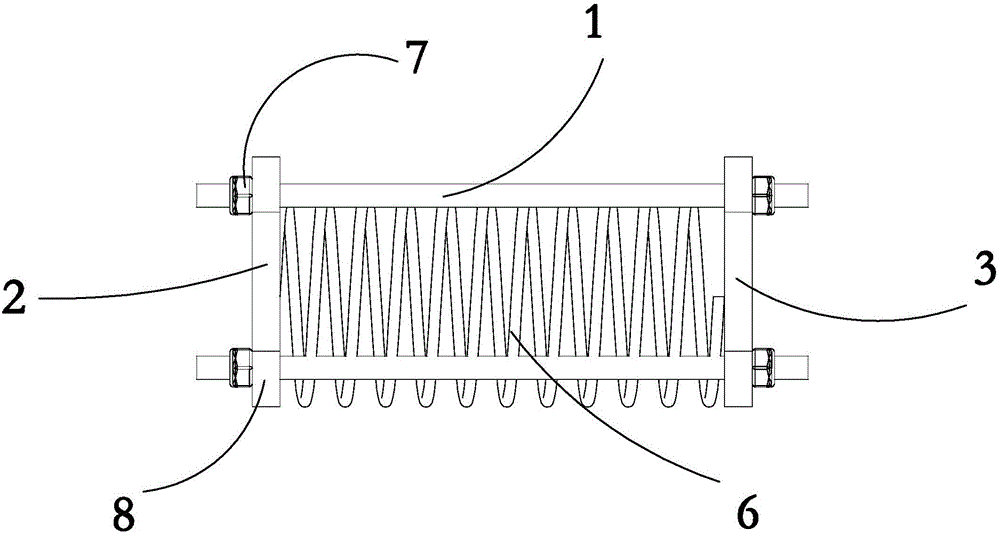
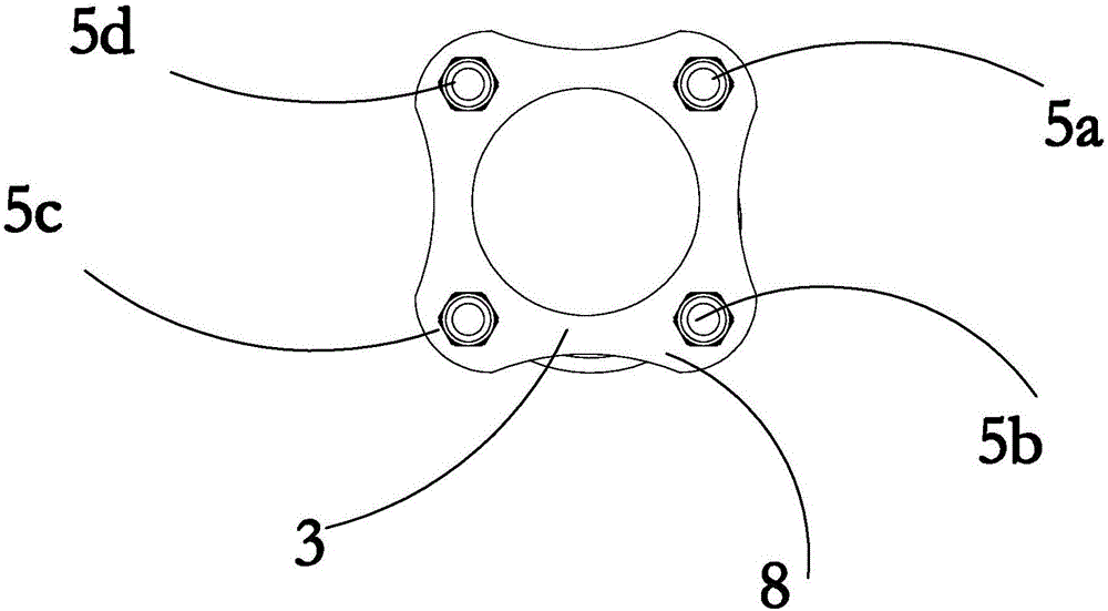
[0015] The invention is mainly applied to the dyeing support of filaments or yarns in laboratory samples. figure 1 , figure 2 The shown preferred embodiment filament or yarn laboratory small sample dyeing support includes a support assembly, and the support assembly includes at least one support column 1, a first support plate 2 and a second support plate 3 with a fixed or adjustable spacing, The support column 1 is connected to the first support plate 2 and the second support plate 3, and the outer periphery of the first support plate 2 is distributed with four first winding columns 4a, 4b, 4c, 4d (4d such as image 3 As shown), four second winding posts 5a, 5b, 5c, 5d are distributed on the outer periphery of the second support plate 3 . The four first winding posts 4a, 4b, 4c, 4d are evenly distributed along the edge of the first support plate 2, and th...


PUM


Abstract

The invention discloses a small sample dyeing bracket for a filament / yarn laboratory.The small sample dyeing bracket comprises a supporting assembly.The supporting assembly comprises one or more supporting stand columns, a first supporting plate and a second supporting plate, wherein the interval between the first supporting plate and the second supporting plate is fixed or adjustable, the supporting stand columns are connected to the first supporting plate and the second supporting plate, the periphery of the outer side of the first supporting plate is provided with a plurality of first wrapping posts, and the periphery of the outer side of the second supporting plate is provided with a plurality of second wrapping posts.The small sample dyeing bracket has the advantages that the structure is simple, operation is simple and convenient, and winding thickness of filament or yarn can be reduced, so that the situation that filament or yarn covers each other is reduced to the maximum degree, dye liquor can evenly and effectively penetrate all parts of fibers, the even dyeing effect is achieved, and the chance of mutual winding of filament or yarn is reduced.

Description

technical field [0001] The invention relates to a dyeing support, in particular to a filament or yarn laboratory sample dyeing support. Background technique [0002] There are usually two types of dyeing supports for filament or yarn laboratories: one is a flat support, which adjusts the length of filaments or yarns through slide rail screws, but when more filaments or yarns are wound , threading back and forth at the first and last two winding positions will cause the yarns to overlap and cover each other, which will increase the thickness of the wrapped yarns, which will easily cause the inner filaments or yarns to be difficult to be saturated and colored by the dye solution, resulting in color difference between the inner and outer layers , and are easily entangled with each other. The other is a spring-type support, which adjusts the length of the filament or yarn by rotating the spring, but the stainless steel sheets are used as baffles on both sides of the top of the ...

Claims


Application Information

Patent Timeline
IPC IPC(8): D06B23/04D06B23/10
CPCD06B23/04D06B23/10
Inventor 杨梅王炜崔海熊申阳
Owner ZHEJIANG TEXTILE & FASHION COLLEGE
Learn More