Column Flange Post-tensioned Steel and Concrete Partial Composite Frame-Steel Plate Shear Wall Structure

A steel plate shear wall and post-tensioning technology, applied to walls, building components, building structures, etc., can solve problems such as loss of strong anchor frame, limited range of constraints, large residual stress and residual deformation, etc., to improve bearing capacity And anti-seismic hysteresis performance, high safety and reliability, convenient and quick construction

Active Publication Date: 2018-02-27
西安建筑科大工程技术有限公司
View PDF6 Cites 0 Cited by
  • Summary
  • Abstract
  • Description
  • Claims
  • Application Information

AI Technical Summary

Problems solved by technology

[0004] Through the research on the steel and concrete partial composite frame-steel plate shear wall structure, the following problems exist: (1) In the connection of ordinary transverse tie rods in steel and concrete partial composite structural columns, due to the spot welding of the transverse connection tie rods on the wing On the inner side of the edge, a large residual stress and residual deformation will be generated at the spot weld, and the weld seam is more likely to crack, which may cause the transverse tie rod to withdraw from work in advance
(2) When the transverse tie rods are firmly connected to the flanges, due to the limited range of spot welding on the flanges, the damage to the steel and concrete composite columns in the structure is first caused by local buckling of the flanges between the transverse tie rods of the H-shaped steel , the inner flange is more serious, and the simple transverse tie rod connection form cannot effectively restrain the local buckling of the flange under the condition of a certain amount of steel
Some composite columns of steel and concrete are destroyed in advance, losing the role of strong anchor frame of the steel plate shear wall structure, and some composite frames of steel and concrete degenerate into steel frames, and the overall structure may not be able to bear larger loads, which limits its application in the project. Got to promote the application

Method used


Image

  • Column Flange Post-tensioned Steel and Concrete Partial Composite Frame-Steel Plate Shear Wall Structure
  • Column Flange Post-tensioned Steel and Concrete Partial Composite Frame-Steel Plate Shear Wall Structure
  • Column Flange Post-tensioned Steel and Concrete Partial Composite Frame-Steel Plate Shear Wall Structure

Examples


Embodiment Construction

[0026] The present invention is described in further detail below in conjunction with accompanying drawing:

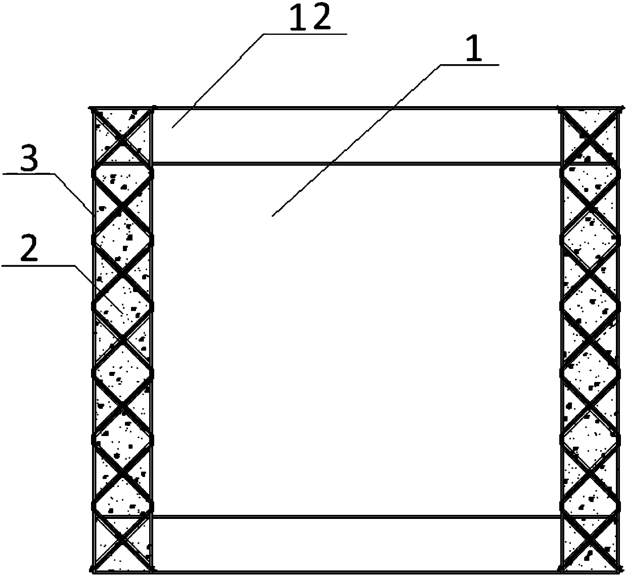
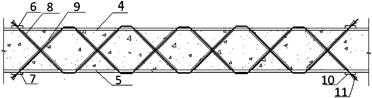
[0027] refer to figure 1 and figure 2According to the present invention, the frame-steel plate shear wall structure composed of post-tensioned steel and concrete part of the column flange includes the inner filling steel plate wall 1, the column H-shaped steel 3, the beam H-shaped steel 12, the first steel wire 6, and the second steel wire 7 , a number of first steel sleeves 8 and a number of second steel sleeves 9, the column H-shaped steel 3 is fixed on the side of the inner filling steel plate wall 1, the beam H-shaped steel 12 is fixed on the top surface of the inner filling steel plate wall 1; the column H-shaped steel 3 It consists of the first flange 4, the second flange 5 and the web, wherein the two ends of the web are respectively connected to the middle of the side of the first flange 4 and the middle of the side of the second flange 5; the first flange 4...


PUM


Abstract

The invention discloses a column flange post-tensioning steel-concrete partial combination frame-steel plate shear wall structure, which comprises a steel plate infill wall, a column H-shaped steel, a beam H-shaped steel, a first steel wire, a second steel wire, a plurality of first steel sleeves and a plurality of second steel sleeves, wherein the column H-shaped steel is fixed in the side face of the steel plate infill wall, and the beam H-shaped steel is fixed in the top surface of the steel plate infill wall. According to the column flange post-tensioning steel-concrete partial combination frame-steel plate shear wall structure, local buckling of a column flange can be effectively reduced, and the bearing capability of a column can be ensured.

Description

technical field [0001] The invention relates to a shear wall structure, in particular to a frame-steel plate shear wall structure composed of a post-tensioned steel and concrete part of a column flange. Background technique [0002] The steel plate shear wall structure is a new type of lateral force-resisting system with the steel plate embedded in the steel frame as the basic structural unit, which evolved and developed on the basis of the theory of thin-web beams. The steel plate shear wall has the following good superior properties: ①The initial lateral stiffness is large, the hysteretic performance is stable, the energy dissipation capacity is strong, the ductility is large, and the deformation resistance under cyclic load is good. ②For the steel frame-reinforced concrete core tube structure, if the core tube is changed to a steel plate wall structure, its stiffness and ductility can be significantly improved, and the matching with the outer frame material, ductility, an...

Claims


Application Information

Patent Timeline
Patent Type & Authority Patents(China)
IPC IPC(8): E04B2/58
CPCE04B2/58
Inventor 于金光郑春明王雪军郝际平
Owner 西安建筑科大工程技术有限公司
Why Eureka
Try Eureka