Oil pipe cleaner

A descaling device and tubing technology, which can be used in cleaning equipment, wellbore/well parts, earthwork drilling and production, etc., and can solve the problems of descaling ability and other problems

Inactive Publication Date: 2016-07-13
PETROCHINA CO LTD
View PDF7 Cites 0 Cited by
  • Summary
  • Abstract
  • Description
  • Claims
  • Application Information

AI Technical Summary

Problems solved by technology

[0012] The present invention aims to provide an oil pipe descaling device to solve the problem in the prior art that the descaling ability of the oil pipe descaling device decreases after being used for a period of time

Method used


Image

  • Oil pipe cleaner
  • Oil pipe cleaner
  • Oil pipe cleaner

Examples


Embodiment Construction

[0037] It should be noted that, in the case of no conflict, the embodiments in the present application and the features in the embodiments can be combined with each other. The present invention will be described in detail below with reference to the accompanying drawings and examples.

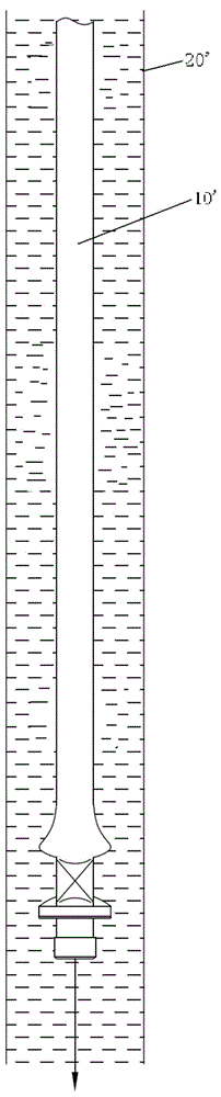
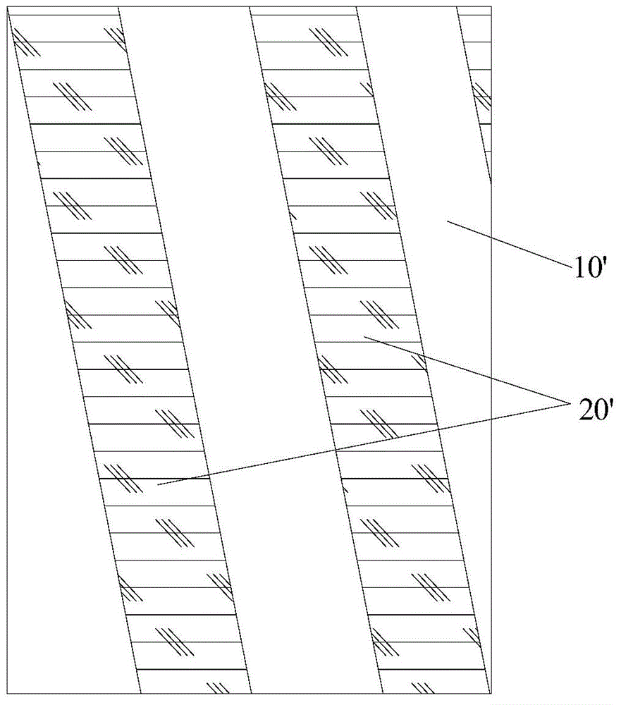
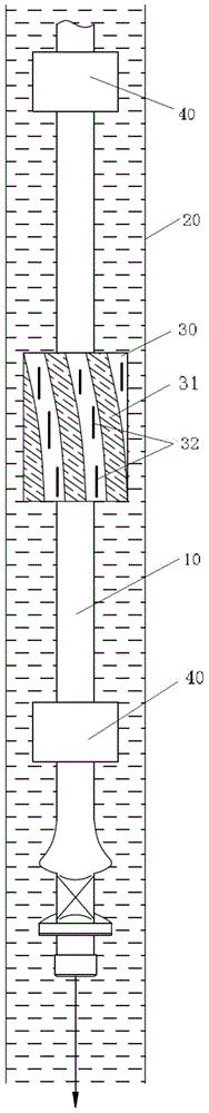
[0038] Such as image 3 As shown, the oil pipe descaling device of this embodiment includes: a decontamination member, which is in the shape of a sleeve and is slidably mounted on the drawer rod 10 . The decontamination member 30 includes an inner surface and an outer surface, the outer surface is provided with a chute 31 which is angled to the axial direction of the drawer rod 10 , and the outer surface is provided with a first rib 32 .

[0039] Applying the technical solution of this embodiment, the sleeve-shaped decontamination member is slidably installed on the drawer rod 10 , and the decontamination member can move along the extension direction of the drawer rod 10 . The decontamination...


PUM


Abstract

The invention provides an oil pipe cleaner comprising a scrubbing member in a sleeve shape; the scrubbing member sleeves on a sucker rod (10), and comprises an inner surface and an outer surface, wherein the outer surface is provided with oblique slots (31) having an angle with the axis of the sucker rod (10), and provided with first convex ribs (32); the oil pipe cleaner can effectively solve the problems in the prior art that an oil pipe cleaner has reduced descaling capability after being used for certain period.

Description

technical field [0001] The invention relates to the technical field of pumping units, in particular to an oil pipe descaling device. Background technique [0002] The working principle of the pumping unit is that the power machine transmits the high-speed rotary motion to the crank shaft through the belt and the reduction box, and drives the crank to rotate at a low speed. The crank drives the beam to swing up and down through the connecting rod and the beam. The rope hanger hung on the donkey's head drives the sucker rod string to reciprocate. [0003] The lower end of the pumping unit is connected to the oil well pump. When the sucker rod moves upward and drives the piston upward, the floating valve is closed by the pressure of the liquid column above the piston in the oil pipe, and the liquid is discharged during the stroke of the piston. Due to the pressure drop in the pump barrel, the fixed valve is pushed open by the pressure of the liquid column in the annular space...

Claims


Application Information

Patent Timeline
Patent Type & Authority Applications(China)
IPC IPC(8): E21B37/00
Inventor 何帆代星王晓沈勇王华
Owner PETROCHINA CO LTD
Why Eureka
Try Eureka