Flue gas denitration multi-pollutant cooperative treatment equipment and use method thereof

A pollutant and denitrification technology, which is applied in gas treatment, separation methods, chemical instruments and methods, etc., can solve the problems of easy entry of water, inconvenient cooling treatment, and inability to realize energy recovery and utilization.

Inactive Publication Date: 2020-10-27
ANHUI XINCHUANG ENERGY SAVING & ENVIRONMENTAL PROTECTION SCI & TECH
View PDF5 Cites 0 Cited by
  • Summary
  • Abstract
  • Description
  • Claims
  • Application Information

AI Technical Summary

Problems solved by technology

[0004] The purpose of the present invention is to provide a flue gas denitrification multi-pollutant cooperative treatment equipment and its use method to solve the problem of de-stocking the flue gas through the SCR denitrification reactor during the use of the existing sintering machine flue gas denitrification device. The heat exchanger does not have a conical plate structure, the water after heat exchange cannot enter the outside of the conical plate, and the water easily en

Method used


Image

  • Flue gas denitration multi-pollutant cooperative treatment equipment and use method thereof
  • Flue gas denitration multi-pollutant cooperative treatment equipment and use method thereof
  • Flue gas denitration multi-pollutant cooperative treatment equipment and use method thereof

Examples


Embodiment Construction

[0031] The technical solutions of the present invention will be clearly and completely described below in conjunction with the embodiments. Apparently, the described embodiments are only some of the embodiments of the present invention, not all of them. Based on the embodiments of the present invention, all other embodiments obtained by persons of ordinary skill in the art without creative efforts fall within the protection scope of the present invention.

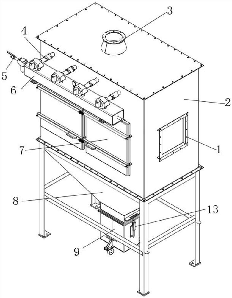
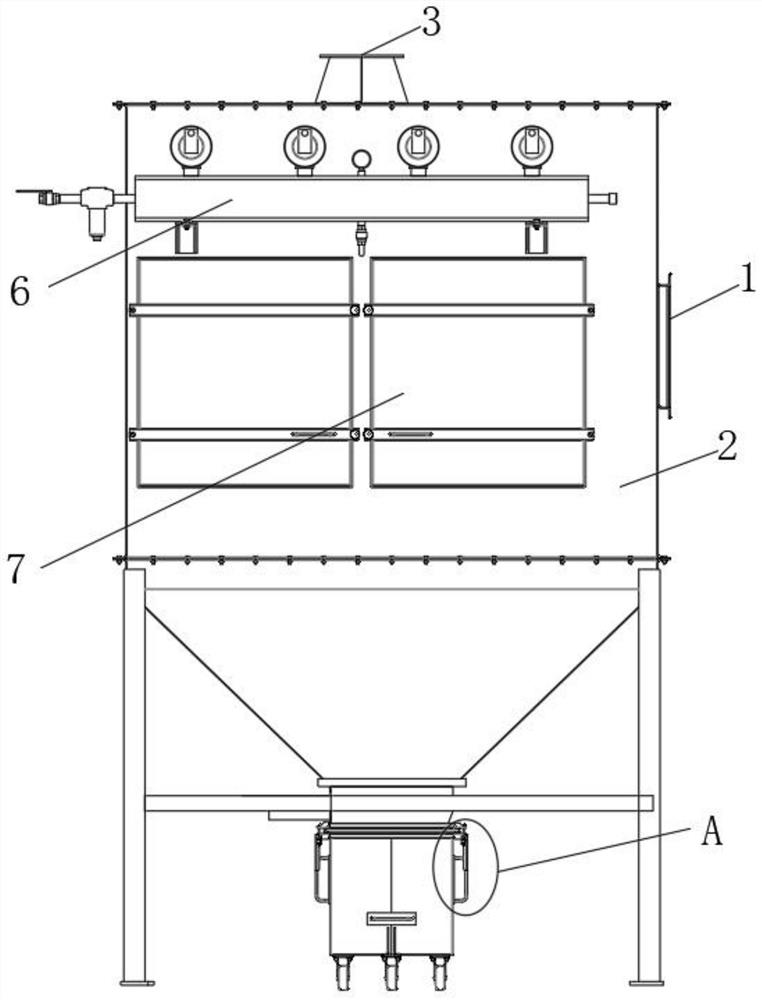
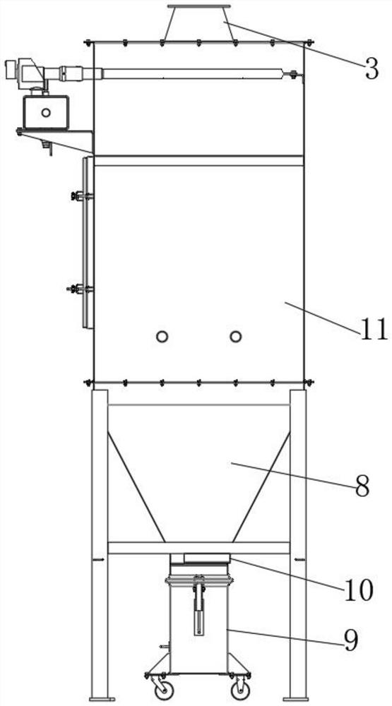
[0032] Such as Figure 1-7As shown, a flue gas denitrification and multi-pollutant cooperative treatment equipment includes a working box 2 and a discharge bin 8. A water tank 6 is fixedly arranged on the side wall of the working box 2, and a water inlet pipe is arranged at one end of the water tank 6. 5. Several cooling pipes 4 are arranged on the top of the water tank 6, one end of each cooling pipe 4 is arranged on the top surface of the water tank 6 and communicates with the inside of the water tank 6, and the other end...


PUM


Abstract

The invention discloses flue gas denitration multi-pollutant cooperative treatment equipment. The equipment comprises a working box and a discharging bin, a water tank is fixedly arranged on the sidewall of one side of the working box, a water inlet pipe is arranged at one end of the water tank, a plurality of cooling pipes are arranged at the top of the water tank, impurities in the flue gas cannot enter an SCR denitration reactor, the impurities fall into the discharging bin and then are accumulated on a material sealing plate through the discharging bin, after denitration is completed, a hydraulic cylinder controls the outer side of a piston rod cylinder body in the hydraulic cylinder to move, a piston rod pushes a hook plate to rotate, so that a rotation shaft rotates, then, a material sealing plate rotates, impurities on the material sealing plate fall into a material receiving box, after the material receiving box is full of the collected impurities, the material sealing plate is closed, buckles are opened, the side wall of the material receiving box is pushed, and the material receiving box is moved out from the lower portion of a discharging pipe through rollers, so that workers can conveniently conduct unified treatment on the impurities, meanwhile, the equipment is guaranteed to continuously conduct purification work, and the working efficiency is improved.

Description

technical field [0001] The invention relates to the field of sintering machine flue gas purification equipment, in particular to a flue gas denitrification and multi-pollutant collaborative treatment equipment and a use method thereof. Background technique [0002] The sintering machine is suitable for the sintering operation of large-scale ferrous metallurgical sintering plants, and is mainly suitable for the sintering treatment of iron ore powder in large and medium-sized sintering plants. When the sintering machine is in use, it will produce a large amount of harmful fumes, which need to be purified. The present invention proposes to pass the sintering flue gas through the electric precipitator, pass through the sintering main exhaust fan, and then enter the SDA desulfurization tower for desulfurization. The temperature of the gas is raised, and then the flue gas is further heated to the denitrification reaction temperature through the supplementary combustion device, an...

Claims


Application Information

Patent Timeline
IPC IPC(8): B01D53/86B01D53/56B01D53/34
CPCB01D53/343B01D53/8628B01D2258/0283
Inventor 胡笳李丰夏勇军胡新华杨凡吴朝刚包自力方辉杨洪姜梦溪
Owner ANHUI XINCHUANG ENERGY SAVING & ENVIRONMENTAL PROTECTION SCI & TECH
Why Eureka
Try Eureka