High-efficient multi-stage cyclone self-cleaning separator and application method

A separator and high-efficiency technology, applied in separation methods, chemical instruments and methods, filtration separation, etc., can solve the problems of losing the filtering effect of the filter, reducing the filtering area of ​​the sand control filter, and shortening the separation effect of the separator.

Active Publication Date: 2016-07-13
HENAN DONGFANGLONG MACHINE MFR
View PDF7 Cites 5 Cited by
  • Summary
  • Abstract
  • Description
  • Claims
  • Application Information

AI Technical Summary

Problems solved by technology

[0002] At present, in the sand control separator used on oil wells, the sand control filter screen is covered on the sand control inner tube. Although there is a certain gap between the sand control filter screen and the sand control inner tube, the sand control filter screen is easily absorbed by the pump for a certain period of time. On the sand control inner pipe, the filter area of ​​the sand control filter is reduced, and the suction force of the sand control filter is increased. The filter screen of the oil inlet channel with a small area is easily damaged by the suction of the oil well pump, and the filter screen is easy to lose. Filtration, fine silt enters the pump barrel through the damaged filter, causing the pump to stop production and shorten the separation effect of the separator

Method used


Image

  • High-efficient multi-stage cyclone self-cleaning separator and application method
  • High-efficient multi-stage cyclone self-cleaning separator and application method
  • High-efficient multi-stage cyclone self-cleaning separator and application method

Examples


Embodiment 1

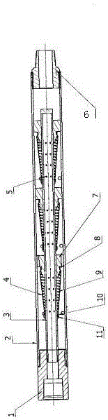
[0014] Embodiment 1, the present invention is made up of upper joint 1, outer pipe 2, inner pipe 3, filter screen 4, lower joint 6, spring support 7, filter screen large hoop 8, spring 9, filter screen small hoop 10, The upper fixing ring 11 is connected, the upper end of the outer tube 2 is connected with the upper joint 1, and the lower end of the outer tube 2 is connected with the lower joint 6; there is an inner tube 3 in the middle of the outer tube 2; the spring support 7 is respectively fixed on the inner tube 3 the outer periphery of the spring 9; the big end of the spring 9 is fixed on the spring support 7; the small end of the spring 9 is fixed on the upper fixed ring 11, the slip ring is on the outer periphery of the inner tube 3, the filter screen 4 is at the outer end of the spring 9, and the upper end of the filter screen 4 Be fixed on slip ring periphery with filter screen small hoop ring 10, filter screen 4 lower ends are fixed on spring support 7 outer peripher...

Embodiment 2

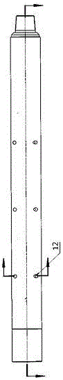
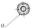
[0015] Embodiment 2. The upper end of the outer tube 2 is provided with an outer tube liquid inlet hole 12, and the outer tube liquid inlet hole 12 is a circumferential tangential liquid inlet hole.

Embodiment 3

[0016] Embodiment 3. The inner pipe 3 is provided with inner pipe liquid inlet holes 5 at the upper and lower sides; the liquid outlet hole of the inner pipe 3 communicates with the liquid inlet hole of the oil well pump.


PUM


Abstract

The invention discloses a high-efficient multi-stage cyclone self-cleaning separator and an application method, relates to the sand control technique of oil well pumps and solves the problems in the prior art. The structural relationship of the separator lies in that an upper connector is connected to the upper end of an outer tube, and a lower connector is connected to the lower end of the outer tube; an inner tube is arranged in the middle of the outer tube; spring supports are respectively fixed on the periphery of the inner tube; big ends of springs are fixed on the spring supports; small ends of the springs are fixed on upper fixed rings, slip rings are arranged on the periphery of the inner tube, filter screens are arranged at the outer ends of the springs, the upper ends of the filter screens are fixed on the peripheries of the slip rings by filter screen small hoop rings, and the lower ends of the filter screens are fixed on the peripheries of the spring supports by filter screen large hoop rings.

Description

technical field [0001] The invention relates to sand control technology of an oil well pump, in particular to a multi-stage high-efficiency cyclone self-cleaning separator and an application method. technical background [0002] At present, in the sand control separator used on oil wells, the sand control filter screen is covered on the sand control inner tube. Although there is a certain gap between the sand control filter screen and the sand control inner tube, the sand control filter screen is easily absorbed by the pump for a certain period of time. On the sand control inner pipe, the filter area of ​​the sand control filter is reduced, and the suction force of the sand control filter is increased. The filter screen of the oil inlet channel with a small area is easily damaged by the suction of the oil well pump, and the filter screen is easy to lose. Filtration, fine silt enters the pump barrel through the damaged filter screen, causing the pump to stop production and sh...

Claims


Application Information

Patent Timeline
IPC IPC(8): E21B43/38B01D33/00B01D33/54
CPCB01D33/00B01D33/54B01D2201/0461E21B43/38
Inventor 别新云张自平张艳华龚星云
Owner HENAN DONGFANGLONG MACHINE MFR
Why Eureka
Try Eureka