Safety can for preventing explosion of liquefied petroleum gas cylinder

A liquefied petroleum gas and safety tank technology, which is applied to the purpose of gas treatment/storage, the method of container discharge, gas/liquid distribution and storage, etc. The effect of eliminating safety hazards, avoiding temperature increases, and reducing the possibility of explosions

Active Publication Date: 2016-07-13
湖南佳创能源工程设计研究院有限公司
View PDF8 Cites 2 Cited by
  • Summary
  • Abstract
  • Description
  • Claims
  • Application Information

AI Technical Summary

Problems solved by technology

[0002] Existing liquefied petroleum gas cylinders leak liquefied petroleum gas due to improper operation or quality problems of the cylinder itself during use, resulting in waste of liquefied petroleum gas, and even ignited by external igniting factors to explode, causing casualties and property losses. To avoid such accidents, designers usually focus on improving the operation optimization of the steel cylinder itself and the improvement of the manufacturing process, ignoring the external protection measures, even if there are external protection measures, the effect is not good

Method used


Image

  • Safety can for preventing explosion of liquefied petroleum gas cylinder
  • Safety can for preventing explosion of liquefied petroleum gas cylinder
  • Safety can for preventing explosion of liquefied petroleum gas cylinder

Examples


Embodiment Construction

[0022] The principles and features of the present invention are described below in conjunction with the accompanying drawings, and the examples given are only used to explain the present invention, and are not intended to limit the scope of the present invention.

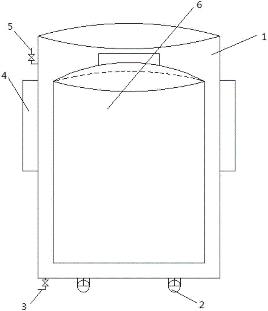
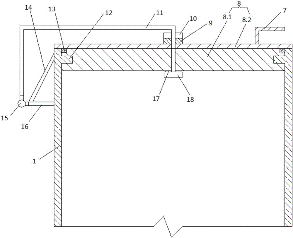
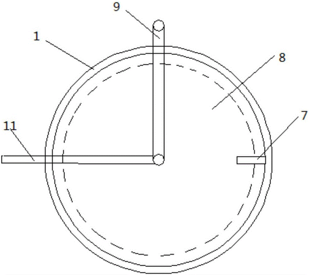
[0023] Such as figure 2 , image 3 and Figure 5 As shown, an explosion-proof safety tank for liquefied petroleum gas cylinders includes a tank body 1 and a tank cover 8, the tank cover 8 is a T-shaped plug cover, and the shoulder 8.2 of the tank cover 8 covers the opening at the top of the tank body 1 , the plug portion 8.1 of the tank cover 8 extends into the tank body 1 from the opening at the top of the tank body 1, and the plug portion 8.1 of the tank cover 8 is sleeved with a first sealing ring 13 near the shoulder 8.2 of the tank cover 8; The upper part of the outer wall of the body 1 is fixedly provided with a support rod 16, and the middle part of the tank cover 8 is vertically rotated to be provided wit...


PUM


Abstract

The invention relates to a safety can for preventing an explosion of a liquefied petroleum gas cylinder. The safety can comprises a can body and a can cover, wherein a supporting rod is fixedly arranged on the upper part of the outer side wall of the can body; a connecting rod is vertically rotatably arranged on the middle part of the can cover; the can cover can peripherally rotate around the connecting rod and at a top opening of the can body; the upper end of the connecting rod is bent toward the outer side of the can body and the connecting rod is hinged with the supporting rod through a hinge located at one end, away from the can body, of the supporting rod; an opening handle is fixedly arranged at the top of the can cover; a plurality of fixture blocks are fixedly arranged along the peripheral direction of the inner wall of the top opening of the can body; clamping slots corresponding to the fixture blocks are formed in the peripheral side wall of a plug part of the can cover, respectively; gaps are formed between the adjacent clamping slots and in the peripheral side wall of the plug part of the can cover; after the gaps are rotated along with the can cover till the corresponding fixture blocks are located in the corresponding gaps, the fixture blocks are separated from the plug part of the can cover through the gaps; an airtight handle extending toward the outer side of the can body is arranged at the top of the can cover. The safety can has beneficial effects of simple structure, convenience in operation, quick opening and closing and excellent pressure-bearing and airtight property.

Description

technical field [0001] The invention relates to an explosion-proof device for a liquefied petroleum gas cylinder, in particular to an explosion-proof safety tank for a liquefied petroleum gas cylinder. Background technique [0002] Existing liquefied petroleum gas cylinders leak liquefied petroleum gas due to improper operation or quality problems of the cylinder itself during use, resulting in waste of liquefied petroleum gas, and even ignited by external igniting factors to explode, causing casualties and property losses. To avoid such accidents, designers usually focus on improving the operation optimization of the steel cylinder itself and the improvement of the manufacturing process, ignoring the external protection measures. Even if there are external protection measures, the effect is not good. Contents of the invention [0003] The technical problem to be solved by the present invention is to provide a safety tank with simple structure, convenient operation, fast o...

Claims


Application Information

Patent Timeline
Patent Type & Authority Applications(China)
IPC IPC(8): F17C13/12
CPCF17C13/123F17C2201/056F17C2221/032F17C2260/042
Inventor 黄小美尹鑫林马向阳夏军宝周阳
Owner 湖南佳创能源工程设计研究院有限公司
Why Eureka
Try Eureka