High-speed microscopic defect review method

A defect, high-speed technology, applied in the field of high-speed micro-defect review, can solve the problems of unstable focus, sensor vibration, etc., to achieve the effect of shortening time and high efficiency of review and image acquisition

Active Publication Date: 2016-07-13
苏州睿仟科技有限公司
View PDF7 Cites 0 Cited by
  • Summary
  • Abstract
  • Description
  • Claims
  • Application Information

AI Technical Summary

Problems solved by technology

[0004] like figure 1 As shown, assume that points P1, P2, P3, P4, P5, and P6 are defect points of the wafer. In the traditional process, a straight line scan

Method used


Image

  • High-speed microscopic defect review method
  • High-speed microscopic defect review method

Examples


Embodiment Construction

[0017] The specific implementation manner of the present invention will be described in further detail below by describing the embodiments with reference to the accompanying drawings.

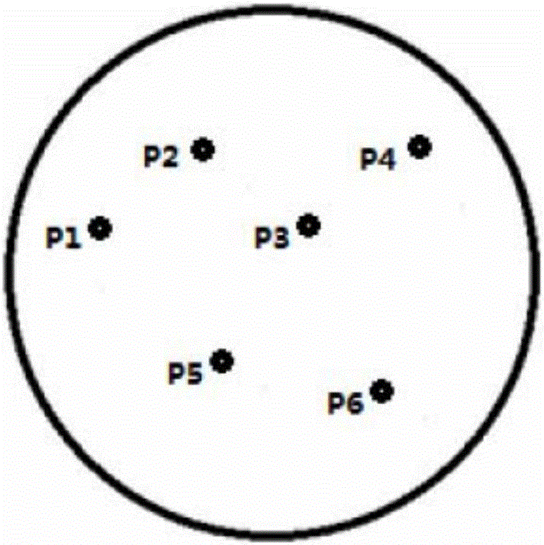
[0018] Use a line scan camera (or an area scan camera with a strobe) to perform low-magnification (1x-5x) image scanning to find the position of the defect on the surface of the inspected object (such as: wafer, flat glass or biomedical slice).

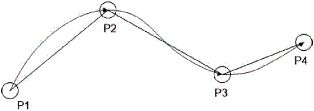
[0019] Such as figure 2 As shown, the defect points on the product are connected into a curve; for example, the four defect points P1, P2, P3, and P4 are connected into a curve in turn, and the camera passes through the four defect points of P1, P2, P3, and P4 along the curve in turn. Take high-speed photography.

[0020] A high-speed area scan camera (CCD or CMOS sensor) equipped with a high-magnification (20x-50x) microscope lens moves at a constant speed along the curve formed by the defect points, and the camera's auto-focus is always on; when ea...


PUM


Abstract

The invention discloses a high-speed microscopic defect review method, comprising the following steps: A), finding positions of defect points by image scanning; B), enabling a camera to automatically focus and be constantly on, and enabling the camera to move at constant speed along a curve of defect points; C), triggering the camera and a flash light upon arrival at each defect point so as to taking photos of the defect points.In the review imaging method, the defect points are passed by at constant speed, the camera automatically focuses and is constantly on, the camera and the flash light are triggered when a lens of the camera arrives near next defect point, the camera never stops upon arrival at each defect point, and thus no vibration is generated; changes occur to the movement direction between the defect points only, vibration caused thereby stops before a sensor arrives at the positions of the defect points, and thus the whole review process has shortened time and high review imaging efficiency.

Description

technical field [0001] The invention relates to the technical field of optical detection, in particular to a high-speed micro-defect review method. Background technique [0002] An effective AOI (automatic optical inspection) system generally consists of two parts: 1) fast low-magnification image scanning to find the location of product surface defects; 2) review with high-magnification microscopic images to determine the nature of the defect and types. [0003] The usual review process is to first obtain the x / y coordinates of multiple defect points, calculate the optimal path, and then review and take pictures point by point. Going from one point to the next is to move in a straight line, first accelerate, then decelerate, stop when it reaches the next defect point, perform autofocus, and then take a picture. One problem with this process is that rapid deceleration can cause vibrations in the motion system, which can cause autofocus instability. Existing solutions are t...

Claims


Application Information

Patent Timeline
IPC IPC(8): G01N21/95G03B13/36
CPCG01N21/95
Inventor 伍祥辰
Owner 苏州睿仟科技有限公司
Why Eureka
Try Eureka