
Magnetic induction intensity measuring method and device

A technology of magnetic induction intensity and measurement method, applied in the direction of the size/direction of the magnetic field, etc., can solve the problems of inability to show, the accuracy of the small magnetic needle demonstration is not high, and it is difficult for students to understand magnetism.

Pending Publication Date: 2016-07-13
上海智勇教育培训有限公司
View PDF0 Cites 2 Cited by
  • Summary
  • Abstract
  • Description
  • Claims
  • Application Information

AI Technical Summary

Problems solved by technology

[0004] Similarly, when we are studying magnetic fields, especially when students are studying magnetism, we can roughly understand the direction and general strength of the magnetic field through the form of magnetic field lines, but it is difficult to obtain the intensity distribution of the magnetic field intuitively and accurately; currently There are two main teaching aids for the demonstration of magnetic lines: small magnetic needles and three-dimensional models of magnetic lines
These two methods have disadvantages: the accuracy of the small magnetic needle demonstration is not high, and a single small magnetic needle can only display the direction of the magnetic field line at a certain point, and cannot show the situation in the entire area; the three-dimensional magnetic line model has limitations and can only Show the distribution of magnetic field lines in some specific magnetic fields, and neither of them can combine the magnetic field strength and magnetic field lines well. These situations make it difficult for many students to understand magnetism, and it is also inconvenient to conduct research on the surrounding magnetic phenomena. observation and research

Method used


Image

  • Magnetic induction intensity measuring method and device
  • Magnetic induction intensity measuring method and device
  • Magnetic induction intensity measuring method and device

Examples


Embodiment Construction

[0061] The present invention will be further described below in conjunction with the accompanying drawings and embodiments.

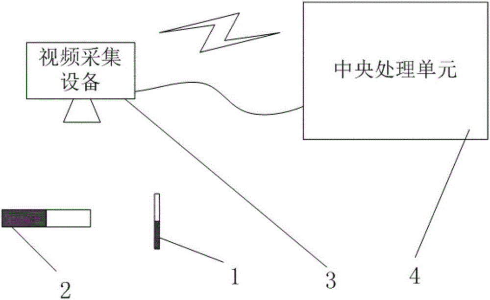
[0062] A method for measuring magnetic induction, utilizing a small magnetic needle 1 and an auxiliary magnet 2 (see image 3 ), the method includes the steps of:

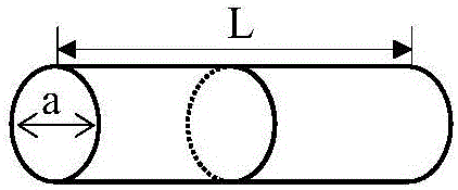
[0063] S1. Set the small magnetic needle 1 at the point to be measured, and define the initial position when the small magnetic needle 1 remains stationary, such as figure 1 As shown, the quality of the small magnetic needle 1 is M, the length is L, and the diameter is a;

[0064] S2. Give the small magnetic needle 1 a radial disturbance force to make it swing less than 5°, and measure its swing period as T;

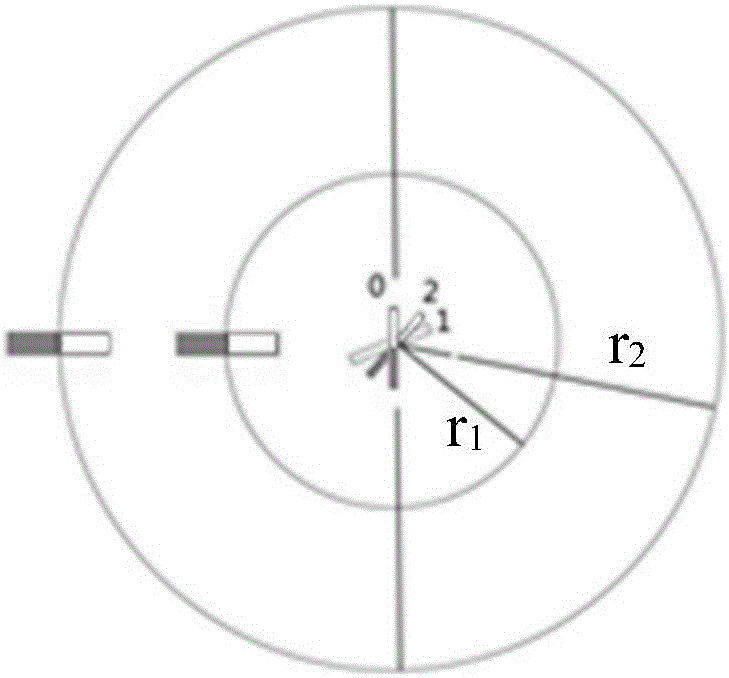
[0065] S3. If figure 2 As shown, an auxiliary magnet 2 is placed on the same level as the small magnetic needle 1, and the auxiliary magnet 2 is arranged on a straight line passing through the center point of the small magnetic needle 1 and perpendicular to the axis of the initial ...


PUM


Abstract

The invention discloses a magnetic induction intensity measuring method and device. The method comprises the following steps: a small magnetic needle and an auxiliary magnet are arranged, and a measurement swing period is T; a first deflection angle alpha1 and a second deflection angle alpha2 are measured at auxiliary positions of a first distance r1 and a second distance r2, and the magnetic induction intensity Bx of a point to be measured is calculated via a specific formula. The device comprises the small magnetic needle, the auxiliary magnet, a video collection device and a central processing unit, wherein the video collection device is used for collecting swing videos of the small magnetic needle and sending the swing videos to the central processing unit, and the central processing unit is used for analyzing and processing the swing video and calculating the magnetic induction intensity Bx of the point to be measured according to the specific formula. The invention also provides magnetic induction intensity measuring tools that are the small magnetic needle and the auxiliary magnet. The small magnetic needle is M in mass, L in length and alpha in diameter. Via use of the magnetic induction intensity measuring method, device and tools that are disclosed in the invention, magnetic field intensity can be accurately measured in a simple and fast manner.

Description

technical field [0001] The invention relates to a measuring method and device, in particular to a measuring method and device for magnetic induction. Background technique [0002] The precise measurement of magnetic induction is of great significance to various fields, including magnetic induction line drawing, marine geomagnetic data, underground pipeline detection, magnetic levitation positioning detection, electromagnetic guidance technology and so on. However, in the prior art, it is often measured by Gaussmeter, magnetometer and other equipment, but the equipment is expensive, and the accuracy is poor due to sensors, measurement angles and other reasons. [0003] Magnetic induction lines and magnetic induction intensity are involved in various fields. Many scholars have studied the measurement and application of magnetic induction intensity. Magnetic induction lines are widely used, especially geomagnetic field navigation and near-Earth space magnetic field detection. ...

Claims


Application Information

Patent Timeline
IPC IPC(8): G01R33/02
CPCG01R33/02
Inventor 孔天煜关大勇
Owner 上海智勇教育培训有限公司
Learn More