
Cup body identification method for food processor

A technology of a food processing machine and an identification method, which is applied in the field of cup body identification of food processing machines, can solve the problems that cannot be realized according to the user's instructions, cannot realize heating, user troubles, etc., achieves convenient operation, and reduces the interference between signals , Accurate signal transmission effect

Active Publication Date: 2016-07-20
JOYOUNG CO LTD
View PDF5 Cites 7 Cited by
  • Summary
  • Abstract
  • Description
  • Claims
  • Application Information

AI Technical Summary

Problems solved by technology

Especially if the cup without heating function is placed on the lower body with heating circuit, the heating function option can be selected on the operation panel, but the heating process cannot be realized
For example, the user places a cup without heating function on the lower body with a heating circuit, and selects the porridge cooking function, which cannot achieve the desired result according to the user's instruction, which brings great trouble to the user.

Method used


Image

  • Cup body identification method for food processor
  • Cup body identification method for food processor
  • Cup body identification method for food processor

Examples


Embodiment 2

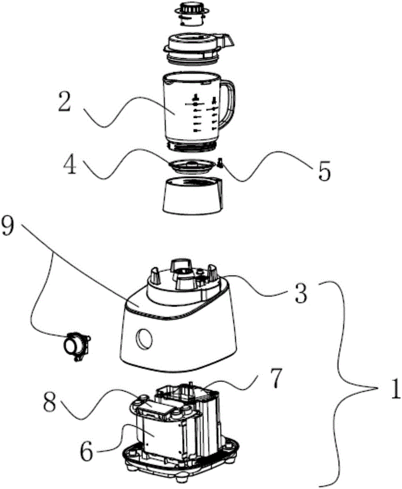
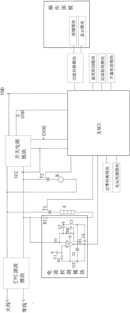
[0059] See attached Figure 4-5 The difference between Embodiment 2 and Embodiment 1 is that the central processing unit includes a master MCU and a slave MCU. The master MCU and the slave MCU perform signal transmission through photoelectric coupling, and the isolation of strong and weak electricity is realized through the setting of the master and slave MCUs. In this embodiment, in order to make the isolation effect better, the main MCU and the function switching module are arranged on the main control board 8, and the slave MCU and the current detection unit are arranged on the power supply board 6, and the detection resistor of the current detection unit R1 is set in the main circuit, and the resistance is preferably constantan wire or manganese copper wire of 10mΩ-100mΩ. When the thyristor T1 is turned on and T2 is turned off, the heating circuit is turned on, and the current flows through the resistor R1. The resistance is large and the current change is small. Therefore...

Embodiment 3

[0066] See attached Figure 6 In this embodiment, the difference between the third embodiment and the first embodiment is that the heating circuit does not have a current detection unit, but the temperature detection module on the cup body and the cup body identification module are electrically connected through the lower coupler 4, according to The change of the temperature detection module judges the presence or absence of the heating element.

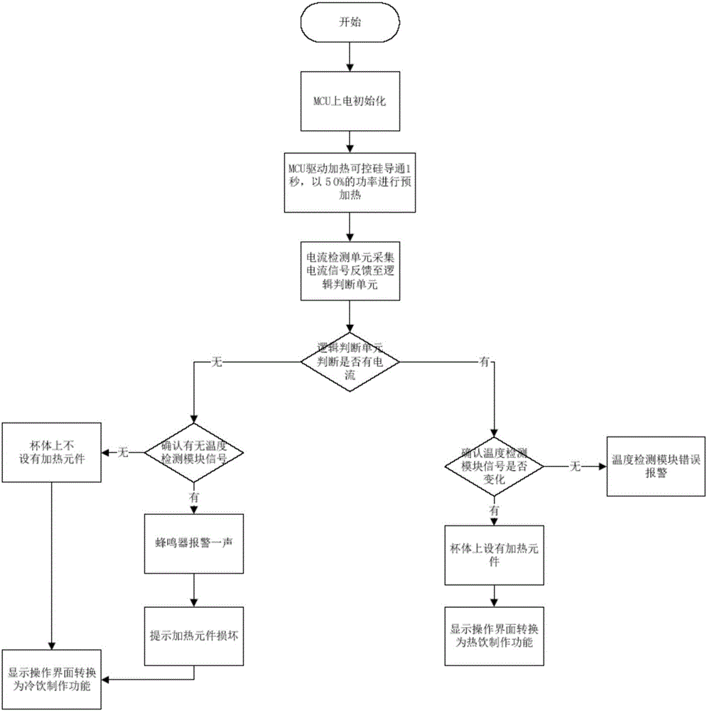
[0067] In this embodiment, the output terminal of the MCU drives the thyristor T1 to conduct heating with 100% power for 2 seconds. If the cup body is equipped with a heating element, after the cup body is heated, the temperature of the temperature detection module will change and will The result is fed back to the MCU, and the main MCU judges the presence or absence of the heating element according to the feedback result of the temperature detection module. If it is judged that the cup body has a heating element, it will switch to t...


PUM


Abstract

The invention provides a cup body identification method for a food processor. A central processing unit drives a heating circuit to be connected for preheating; then a current detection unit acquires current of the heating circuit and sends a feedback signal to the central processing unit, and the central processing unit judges whether a cup body comprises a heating element or not according to the feedback signal; a function switching unit switches functions according to a command sent by the central processing unit, and corresponding functions are displayed through an operation panel. Whether the heating element exists or not is judged through a current detection module, the corresponding functions are displayed on the operation panel, so that function options on the operation panel are adapted to the cup body, misoperation is effectively prevented, and a product is safer to use.

Description

technical field [0001] The invention relates to the technical field of food processing, in particular to a method for identifying a cup body of a food processing machine. Background technique [0002] Cooking machines usually include a material cup and a lower body, some of which have a heating function, and some do not have a heating function. The realization of the heating function requires the cooperation of the lower body and the material cup. If the material cup and the lower body do not match, the heating cannot be realized. Especially if the material cup without heating function is placed on the lower body provided with the heating circuit, the heating function option can be selected on the operation panel, but the heating process cannot be realized. For example, the user places a cup without heating function on the lower body provided with a heating circuit, and selects the porridge cooking function, which cannot achieve the desired result according to the user's in...

Claims


Application Information

Patent Timeline
Patent Type & Authority Applications(China)
IPC IPC(8): A47J43/046A47J43/07
CPCA47J43/046A47J43/07A47J43/0722
Inventor 王旭宁林小财吴华锋
Owner JOYOUNG CO LTD
Learn More