A Ray Tracing Method of Beam Limiter on Z-axis

A ray tracing and beam limiter technology, applied in the field of radiological diagnosis, can solve the problems of irradiation, image quality degradation, meaningless X-rays, etc., to achieve the effect of reducing dose, avoiding X-ray damage, and maintaining a high degree of consistency

Active Publication Date: 2018-12-11
SAINUO WEISHENG SCI & TECH BEIJING
View PDF6 Cites 0 Cited by
  • Summary
  • Abstract
  • Description
  • Claims
  • Application Information

AI Technical Summary

Problems solved by technology

These X-ray beams that are randomly shifted in the Z-axis direction will cause image quality degradation and indirectly cause meaningless X-ray exposure

Method used


Image

  • A Ray Tracing Method of Beam Limiter on Z-axis
  • A Ray Tracing Method of Beam Limiter on Z-axis
  • A Ray Tracing Method of Beam Limiter on Z-axis

Examples


Embodiment Construction

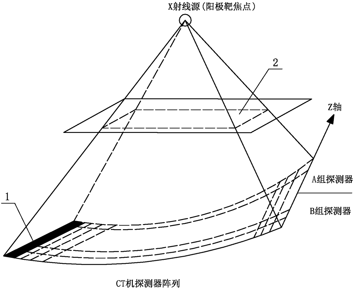
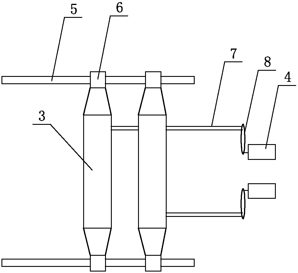
[0024] see figure 1 , figure 2 , a kind of ray tracing method of beam limiter on Z axis, the step of described ray tracing comprises:

[0025] A. The beam limiter reads the detector data of all reference channels 1 of each view of the multi-slice CT machine;

[0026] In this embodiment, the multi-slice CT machine has 32 rows of detectors, each row of detectors has 8 reference channels, a total of 256 reference channels. As shown in the table below.

[0027]

[0028] At least one side of each row of detectors needs to have a ray tracing reference channel. For multiple rows of detectors, the number of reference channels on each layer can be more or less. The more the number, the better the control accuracy. A view is to collect all the channels in the detector once, including the reference channel.

[0029] Further, the reference channel is located at the outermost end of each row of detectors.

[0030] B. The detector data is divided into A group of detector data and ...


PUM


Abstract

The invention relates to a ray tracing method of a beam limiting device on the axis Z.The ray tracing method includes the steps that the beam limiting device reads detector data of all reference channels of each view of multiple layers of CT machines; the detector data is averagely divided into two groups in the Z-axis direction; average values and standard deviations of the two groups of detector data are calculated respectively; a normalized value of the standard deviations of the two groups of detector data is obtained; the fine adjustment distance of an opening of the beam limiting device on the axis Z is calculated according to the normalized value of the standard deviations; the standard deviation of the group A of detector data is compared with that of the group B of detector data, and the moving direction of the opening of the beam limiting device on the axis Z is determined; the beam limiting device controls two tungsten pieces to synchronously move the fine adjustment distance on the Z axis in the moving direction, and ray tracing of the beam limiting device on the Z axis is completed.The beam limiting device can be controlled to move in the Z-axis direction to trace X-ray sources, and meaningless X-ray damage is avoided.

Description

technical field [0001] The invention relates to the technical field of radiation diagnosis, in particular to a ray tracing method of a beam limiter on the Z axis. Background technique [0002] During the scanning process of the computed tomography system (CT), due to the rotation shake of the anode target that generates X-rays and the thermal expansion and contraction of the anode target surface, the focal point will shift, so that the X-ray generated on the anode target surface 101 (focus) The ray beam is randomly offset in the Z axis. The X-ray beam passes through the opening 102 of the beam limiter and the tissues and organs 103 of the human body and then irradiates onto the detector 104 . Even a small offset will produce a large offset in the spatial resolution of the human body / detector after geometric amplification, see Figure 4 . These X-ray beams that are randomly shifted in the Z-axis direction will cause image quality degradation and indirectly cause meaningless...

Claims


Application Information

Patent Timeline
Patent Type & Authority Patents(China)
IPC IPC(8): A61B6/03A61B6/00
CPCA61B6/03A61B6/035A61B6/4021
Inventor 李国旺刘宇飞周宇田季丰
Owner SAINUO WEISHENG SCI & TECH BEIJING
Why Eureka
Try Eureka