A countercurrent chromatographic separation column and chromatograph

A technology of countercurrent chromatography and separation column, applied in the field of countercurrent chromatography separation column, can solve the problems of limited development function of countercurrent chromatography column, difficult to innovate the pipeline structure, and broken pipes, etc., so as to improve and increase the separation efficiency of countercurrent chromatography. Solution interaction force and mixing force, the effect of improving dispensing efficiency

Active Publication Date: 2020-06-02
SHANDONG ANALYSIS & TEST CENT
View PDF6 Cites 0 Cited by
  • Summary
  • Abstract
  • Description
  • Claims
  • Application Information

AI Technical Summary

Problems solved by technology

The countercurrent chromatography separation column with this structure is limited by commercial polytetrafluoroethylene tubes, and it is difficult to innovate in the pipeline structure. limit
At the same time, due to the direct friction between the PTFE pipeline and the support during the winding process, the pipeline is easily damaged and leaks. In addition, when the pipeline is relatively long, the volume of the countercurrent chromatographic separation column after winding will be very large. Big

Method used


Image

  • A countercurrent chromatographic separation column and chromatograph
  • A countercurrent chromatographic separation column and chromatograph
  • A countercurrent chromatographic separation column and chromatograph

Examples


Embodiment 1

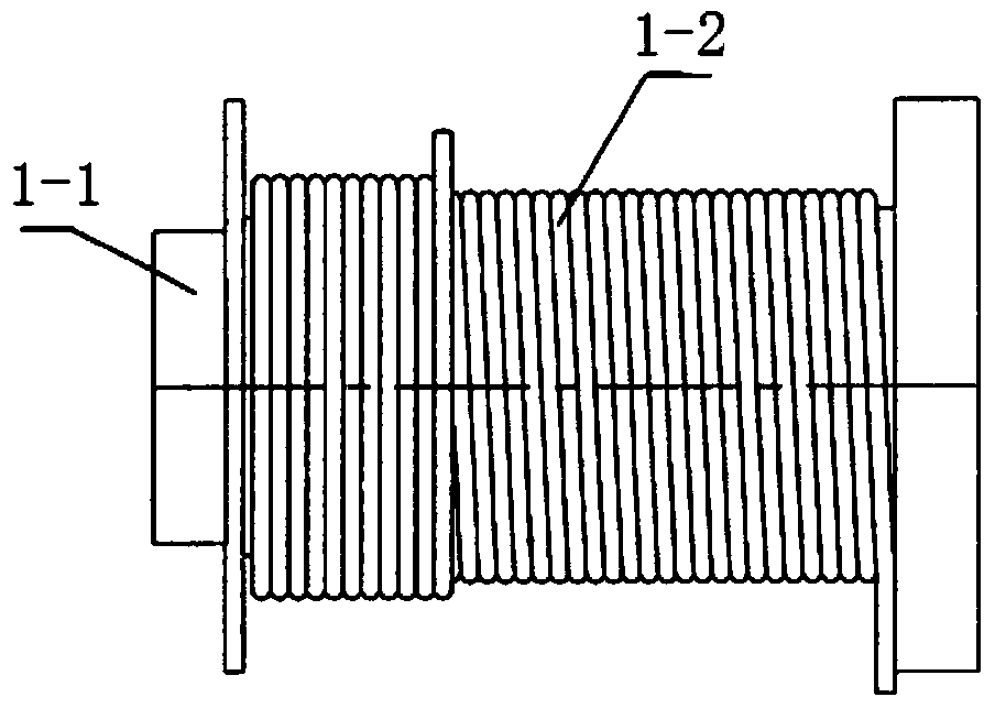
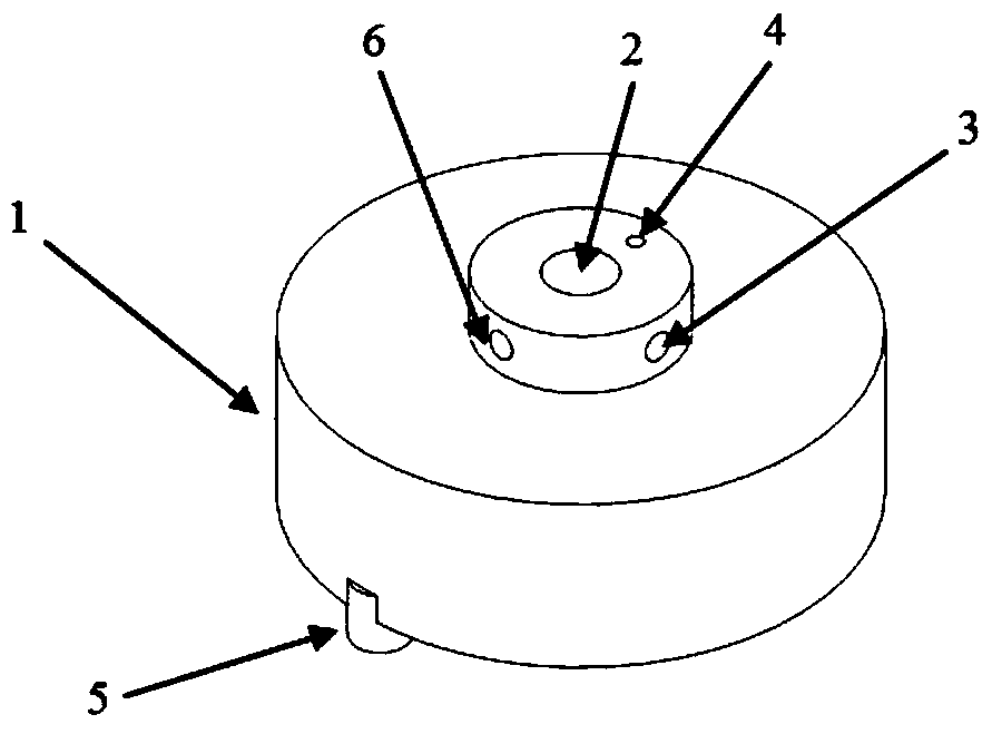
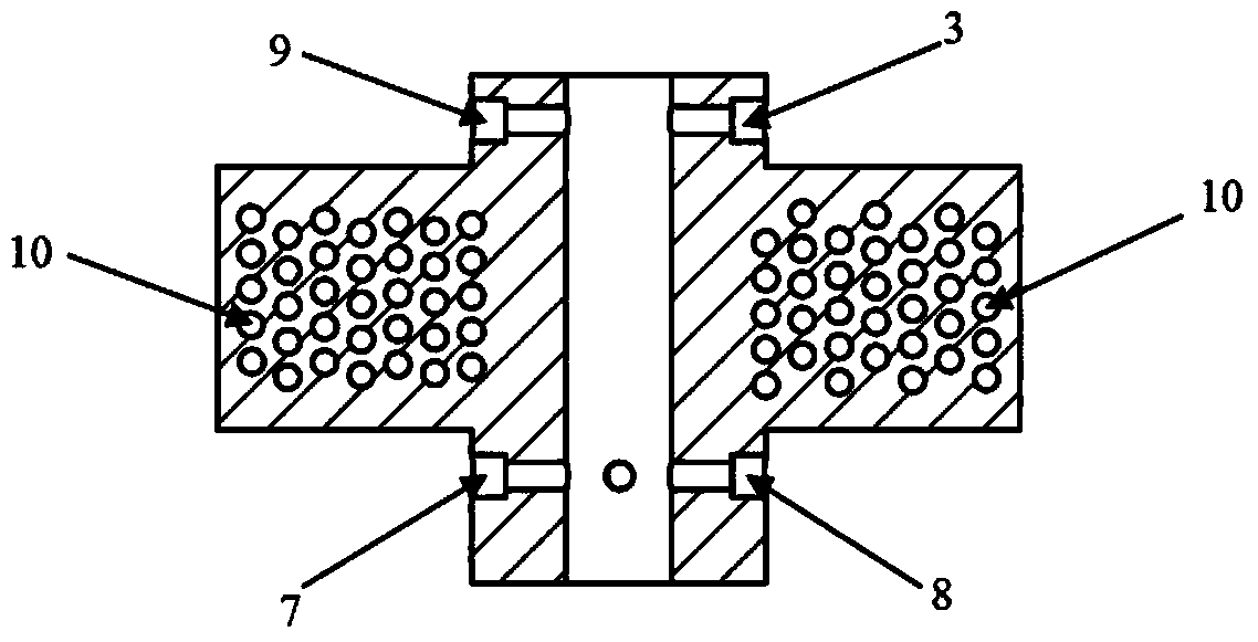
[0026] The structure of the present invention is as figure 2 , image 3 As shown in the figure, the 3D printed countercurrent chromatography separation column has an integrated structure of the pipeline and the support column by 3D printing technology.

[0027] Further, the countercurrent chromatographic separation column 1 is a columnar structure, and a cylindrical protrusion coaxial with the columnar structure is provided at the center of the top and bottom of the columnar structure, and a columnar structure and two cylindrical protrusions are provided along the center of the cylindrical protrusion. The central axis perforation 2 in the center of the shaped protrusion is provided with central axis fixing screw perforations 3, 6, 7, 8, 9 on the sides of the two cylindrical protrusions; the sample inlet 4 is provided on the cylindrical protrusion at the top, There are multiple circles of cylindrical channels 10 used to replace the original pipelines in the columnar structure...

Embodiment 2

[0032] A chromatograph, the countercurrent chromatographic separation column adopts the 3D printed countercurrent chromatographic separation column designed in Example 1.

[0033] Aiming at the technical difficulties existing in conventional countercurrent chromatography separation columns, the present invention develops a countercurrent chromatography separation column based on 3D printing, which can print out tube shapes of any structure through drawing software, and then directly print them through 3D printing technology, and because the tube The road and the supporting column are integrally formed by 3D printing technology, so when the length of the pipeline is as long as that of the prior art, the volume of the separation column of the present invention is obviously smaller than that of the prior art.


PUM


Abstract

The invention discloses a counter-current chromatography separating column and a chromatographic instrument. A pipe and a supporting column of the counter-current chromatography separating column adopt a structure integrally formed with a 3D printing technology; the counter-current chromatography separating column adopts a columnar structure, a cylindrical bulge coaxial with the columnar structure is arranged at each of the top center and the bottom center of the columnar structure, an axial penetrating hole penetrating through the columnar structure and centers of the two cylindrical bulges is formed in centers of the cylindrical bulges, and a sample inlet is formed in the cylindrical bulge at the top; multiple circles of a pipe are arranged in the columnar structure, and a sample outlet is formed in the bottom of the columnar structure. The counter-current chromatography separating column printed in a 3D manner has the advantages that the pipe is not prone to leakage, and the separating column can resist a relatively wide temperature range in a use process.

Description

technical field [0001] The invention relates to a countercurrent chromatographic separation column used in a chromatograph, and specifically discloses a 3D printed countercurrent chromatographic separation column and a chromatograph. Background technique [0002] Conventional countercurrent chromatography separation columns are composed of polytetrafluoroethylene tubes and pipeline supports, for example: the countercurrent chromatography separation columns disclosed in patents with patent numbers 02250372.2, 89221310.8, 201020002148.6, 201120031345.5, 201220647532.4, which include a pipeline support 1 -1 and the polytetrafluoroethylene pipeline 1-2 wound on the pipeline support body 1-1, and the outer layer of the pipeline is fixed with glue, and a plastic or metal shell is placed on the outermost pipeline friction. The countercurrent chromatography separation column with this structure is limited by commercial polytetrafluoroethylene tubes, and it is difficult to innovate ...

Claims


Application Information

Patent Timeline
Patent Type & Authority Patents(China)
IPC IPC(8): B01D15/22G01N30/02G01N30/60
CPCB01D15/22G01N30/02G01N30/606
Inventor 王晓王岱杰刘峰段文娟闫慧娇
Owner SHANDONG ANALYSIS & TEST CENT
Why Eureka
Try Eureka