Temperature control stirring chemical reactor

A chemical reaction and stirring blade technology, which is applied in the direction of mixer accessories, chemical/physical/physical chemical fixed reactors, mixers with rotating stirring devices, etc., can solve the waste of reactant raw materials, affect the life of the device, and the vibration of the reactor and other problems, to achieve the effect of no dead angle of stirring, low manufacturing cost and easy realization

Inactive Publication Date: 2016-07-20
TIANJIN HAOSHI CARPET
View PDF0 Cites 5 Cited by
  • Summary
  • Abstract
  • Description
  • Claims
  • Application Information

AI Technical Summary

Problems solved by technology

[0002] Reactor is an important chemical equipment, its main function is to store or react corresponding chemical substances. When the stirring device in the reactor is working, the installation is not strong enough, which often causes the vibration of the reactor, affects the life of the device itself, and is more likely to cause disasters. At the same time, due to the unreasonable design of the stirring blades, the stirring Insufficient, often the reactants are not fully reacted and discharged as debris, wasting the raw materials of the reactants
[0003] In addition, we understand that many chemical reactions require specific temperature and pressure to achieve the desired effect, otherwise the reaction will not occur, or the desired result will not be obtained. Temperature is very important to chemical reactions. Existing chemical Although the reaction equipment can carry out relatively precise temperature control, its operation is extremely complicated, and because the reaction is exothermic or endothermic during the reaction process, it is difficult to achieve it by artificial control.

Method used


Image

  • Temperature control stirring chemical reactor
  • Temperature control stirring chemical reactor
  • Temperature control stirring chemical reactor

Examples


Embodiment Construction

[0017] The following will clearly and completely describe the technical solutions in the embodiments of the present invention in conjunction with the accompanying drawings in the embodiments of the present invention. Obviously, the described embodiments are only a part of the embodiments of the present invention, rather than all the embodiments. The embodiments of the present invention, and all other embodiments obtained by those of ordinary skill in the art without creative work, fall within the protection scope of the present invention.

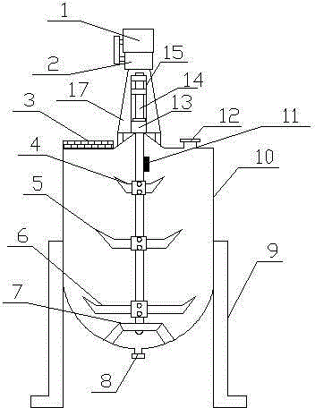
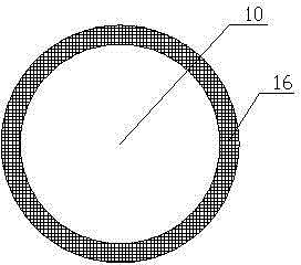
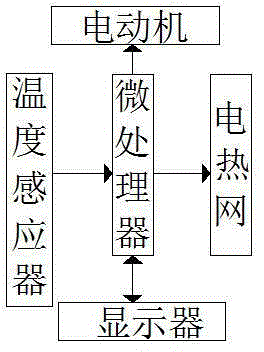
[0018] See Figure 1-3 , The present invention provides a technical solution: a temperature-controlled stirring chemical reaction kettle, comprising a cylindrical kettle body 10, a microprocessor 1, a feed inlet 12 installed at the top side of the kettle body, and an outlet at the bottom of the kettle body The material port 8, the support frame 17 installed above the kettle body and used to fix the driving device, the driving device has a moto...


PUM


Abstract

The invention discloses a temperature control stirring chemical reactor, comprising a cylindrical kettle body, a microprocessor, a feed inlet mounted on one side of the kettle body top, a feed outlet mounted on the bottom of the kettle body, and a support frame installed above the kettle body and used for fixing a driving device. The driving device is provided with, from top to bottom, a motor, a reducer, a coupling and a rotation shaft; the rotation shaft extend downwards into the kettle body, and the a bearing seat is in cup joint to the end of the rotation shaft; the upper portion of the motor is provided with the microprocessor; the rotation shaft in the kettle body is provided with a temperature sensor, a first stirring blade, a second stirring blade and a third stirring blade from top to bottom to form a tower-shaped stirring blade group; and the kettle body shell is internally provided with an electric network. The reactor has the advantages of high efficiency of stirring blade group, no stirring dead corner in the kettle body, stable transmission, heating of the kettle body by the electric network; the microprocessor can control the temperature; and the reactor is simple and strong in structure, low in cost, and easy to implement.

Description

Technical field [0001] The invention relates to a chemical reaction kettle, specifically a temperature-controlled stirring chemical reaction kettle, belonging to the technical field of reaction kettle equipment. Background technique [0002] The reactor is an important chemical equipment. Its main function is to store or provide for the reaction of the corresponding chemical substances. The speed of the chemical reaction mostly depends on the contact area of ​​the reactants. The use of stirring devices can promote the rate of the chemical reaction, but some existing ones The stirring device in the reaction kettle, due to insufficient installation during operation, often causes the reaction kettle to vibrate, affects the life of the device itself, and is more likely to cause disasters. At the same time, the stirring blades are not designed reasonably enough to cause stirring. Insufficient, it often happens that the reactant is not completely reacted and discharged as debris, and t...

Claims


Application Information

Patent Timeline
Patent Type & Authority Applications(China)
IPC IPC(8): B01J19/18B01F7/18B01F15/06
Inventor 汪志发张树军
Owner TIANJIN HAOSHI CARPET
Why Eureka
Try Eureka