Automatic paint spraying device
An automatic painting and spraying gun technology, which is applied in the direction of spraying devices, can solve the problems of increased volume of automatic painting devices, bulky automatic painting devices, inconvenient movement, etc., and achieves the effect of compact structure, small space occupation, and adjustable transmission distance
- Summary
- Abstract
- Description
- Claims
- Application Information
AI Technical Summary
Problems solved by technology
Method used
Image
Examples
Embodiment 1
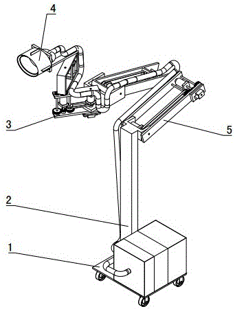
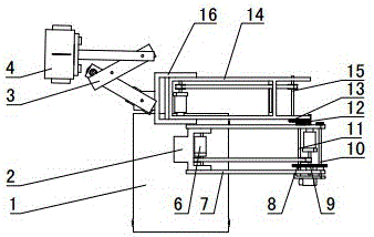
[0036] Such as figure 1 Shown: the support 2 is a vertically arranged square steel, the base 1 is arranged under the support 2, the base 1 is a rectangular steel plate, the area of the base 1 is greater than the cross-sectional area of the support 2, and the support 2 is welded on the base 1, thereby increasing the The area of the contact surface between the automatic painting device and the ground enables the automatic painting device to be placed on the ground more stably, and can also reduce the pressure of the automatic painting device on the ground. The linear push mechanism 5 is installed above the support 2 , and the translation mechanism 3 is installed on the linear push mechanism 5 . The base 1 is provided with rollers to facilitate the movement of the automatic painting device.
[0037] The spray gun is an automatic spray gun, and the spray gun is installed on the translation mechanism 3, and the paint can is also installed on the translation mechanism 3, and th...
Embodiment 2
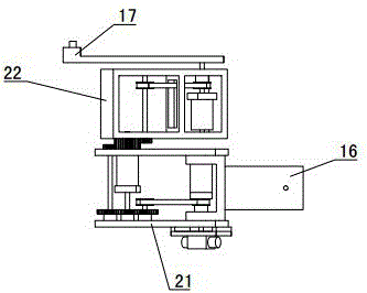
[0057] Such as Figure 4 As shown: the difference between Embodiment 2 and Embodiment 1 is that the translation mechanism 3 includes guide rails 18 and sliders 19 . The guide rail 18 is installed on the translation mechanism installation arm 16 , and the axis of the guide rail 18 is perpendicular to the swing plane of the translation mechanism installation arm 16 . A square chute is provided on the guide rail 18 , and a guide part matched with the chute is provided below the slide block 19 , and the slide block 19 is slidably installed on the guide rail 18 through the guide part. Spray gun is installed on the slide block 19.
Embodiment 3
[0059] Such as Figure 5 As shown: the difference between embodiment 3 and embodiment 2 is that the support 2 is an inverted "L" shape, the lower end of the vertical part of the support 2 is installed on the base 1, and the linear push mechanism 5 is installed at the end of the horizontal part of the support 2 , and push the translation mechanism 3 to move in a direction perpendicular to the translation mechanism 3 in the horizontal plane, thereby completing the paint repair on the horizontal plane.
[0060] There are two linear push mechanisms 5 arranged symmetrically, and the two linear push mechanisms 5 are driven by an electric motor. Two linear propulsion mechanisms are located on the output shaft of the reducer 6 between the first swing arm 7 and the second swing arm 14, and a power distribution gear 20 is installed on the output shaft. The two power distribution gears 20 are meshed, and the motor is connected to one of the power distribution gears. Gears 20 are connect...
PUM
 Abstract
Description
Claims
Application Information
 - R&D
- Intellectual Property
- Life Sciences
- Materials
- Tech Scout
- Unparalleled Data Quality
- Higher Quality Content
- 60% Fewer Hallucinations
Browse by: Latest US Patents, China's latest patents, Technical Efficacy Thesaurus, Application Domain, Technology Topic, Popular Technical Reports.
© 2025 PatSnap. All rights reserved.Legal|Privacy policy|Modern Slavery Act Transparency Statement|Sitemap|About US| Contact US: help@patsnap.com


