A powder spray recovery device

A recovery device, powder technology, applied in the direction of the injection device, etc., can solve the problems of blockage, low recovery efficiency, etc., to achieve the effect of preventing blockage, high recovery efficiency, and convenient operation

Active Publication Date: 2021-04-30
深圳市华信一机械有限公司
View PDF19 Cites 2 Cited by
  • Summary
  • Abstract
  • Description
  • Claims
  • Application Information

AI Technical Summary

Problems solved by technology

However, the recovery efficiency of this equipment is low and it is easy to cause blockage during the recovery process of powder spray paint

Method used


Image

  • A powder spray recovery device
  • A powder spray recovery device
  • A powder spray recovery device

Examples


specific Embodiment approach 1

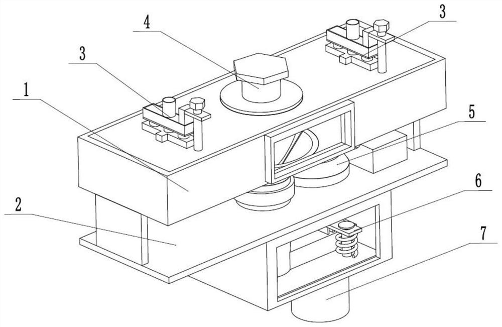
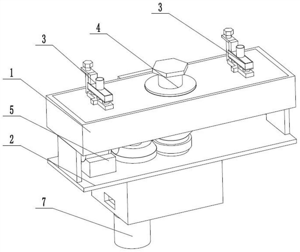
[0031] Such as Figure 1 to Figure 11 As shown, a powder spraying recovery device includes a spraying operation box 1, a powder recovery flow box 2, two spraying operators 3, a spraying fixer 4, a spraying recovery anti-blocking driver 5, a filter brush 6 and a powder recovery cylinder 7. The lower end of the spraying operation box 1 is fixedly connected to the powder recovery flow box 2, and the two spraying operators 3 are respectively slidingly connected to the left and right sides of the upper end of the spraying operation box 1, and the spraying holder 4 is rotatably connected to the spraying operation In the center of the upper end of the box 1, the spraying recycling anti-clogging drive 5 is fixedly connected to the powder recycling flow box 2, the spraying recycling anti-clogging driver 5 is rotatably connected in the spraying operation box 1 and the powder recycling flow box 2, and the lower end of the filter screen brush 6 It is fixedly connected in the powder recove...

specific Embodiment approach 2

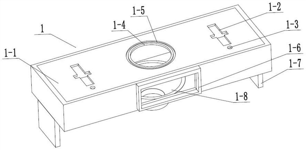
[0033] Such as Figure 1 to Figure 11 As shown, this embodiment will further explain Embodiment 1. The spraying operation box 1 includes an upper operation box 1-1, two limiting cross sliding grooves 1-2, two upper rotating round holes 1-3, a center Add round hole 1-4, plane bearing rotation groove 1-5, upper observation frame 1-6, two connecting plates 1-7 and conical recovery and receiving bobbin 1-8, and both sides of the upper end of upper operation box 1-1 Two limiting cross sliding grooves 1-2 that penetrate up and down are respectively provided with, and the rear sides of the two limiting cross sliding grooves 1-2 are provided with upper rotating round holes 1-3 on the upper operation box 1-1, and the center Add round hole 1-4 to be arranged on the center of the upper end of the upper operation box 1-1, and the outer side of the upper operation box 1-1 is provided with a plane bearing rotation groove 1-5 on the upper operation box 1-1, and an upper observation frame 1-6...

specific Embodiment approach 3

[0035] Such as Figure 1 to Figure 11 As shown, this embodiment will further explain Embodiment 2. The powder recovery flow box 2 includes a lower fixing plate 2-1, a lower recovery flow pipe 2-2, a lower rotating hole 2-3, and a lower observation frame 2 -4. Observation slot 2-5, air discharge rectangular tube 2-6, three sealing sliding slots 2-7, three filter screen seats 2-8, recovery slot 2-9 and external thread connection tube 2-10, The two connection plates 1-7 are fixedly connected to the lower fixed plate 2-1, the lower observation frame 2-4 is fixedly connected to the lower end of the lower fixed plate 2-1, and the lower recovery flow pipe 2-2 is fixedly connected to the lower fixed plate 2-1 and In the lower observation frame 2-4, the lower rotating hole 2-3 is arranged on the lower fixed plate 2-1, and the rear end of the lower observation frame 2-4 is provided with an observation slot 2-5, and the air flow is discharged from the rectangular tube 2-6. The left end ...


PUM


Abstract

The present invention relates to the field of powder spraying, more specifically a powder spraying recovery device, comprising a spraying operation box, a powder recovery flow box, two spraying operators, a spraying fixer, a spraying recovery anti-blocking driver, a filter screen brusher and The powder recovery cylinder, the lower end of the spraying operation box is fixedly connected to the powder recovery flow box, the two spraying operators are respectively slidingly connected to the left and right sides of the upper end of the spraying operation box, and the spraying fixer is rotatably connected to the upper end of the spraying operation box In the center, the spray recovery anti-blocking driver is fixedly connected to the powder recovery flow box; the beneficial effect of the present invention is that the process of spraying paint can be adjusted during the process of powder spraying, and the spraying effect can be guaranteed while preventing powder leakage, and the operation is convenient ;After the multi-layer filter screen isolates the fraction, the airflow flows out and the powder is recovered; in the process of powder recovery, the powder recovery efficiency is high, and at the same time, it prevents powder blockage during the flow recovery process.

Description

technical field [0001] The invention relates to the field of powder coating, in particular to a powder coating recycling device. Background technique [0002] Patent No. CN201410072576.9 discloses a powder recovery device, including a suction mechanism for sucking powder; a cyclone feeder, the cyclone feeder includes a built-in air induction mechanism, connected to the air inlet end of the air induction mechanism and communicated with the suction mechanism The air inlet, the air outlet connected to the air outlet of the air induction mechanism; the powder separation chamber, which includes an inverted "U"-shaped separation channel, and a powder inlet and a powder outlet respectively located at both ends of the separation channel, and the powder inlet It communicates with the air outlet; the silo, the silo includes a shell, and a cover on the top end of the shell, inside the silo is provided a grille located below the cover, and the silo is provided with a grille located abov...

Claims


Application Information

Patent Timeline
Patent Type & Authority Patents(China)
IPC IPC(8): B05B13/02B05B14/43B05B14/48B05B15/50B05B15/68
CPCB05B13/0228B05B14/43B05B14/48B05B15/50B05B15/68Y02P70/10
Inventor 孔芹
Owner 深圳市华信一机械有限公司
Why Eureka
Try Eureka