Clamping device of numerical control machine tool

A technology of CNC machine tools and clamping device, applied in the field of CNC machine tools, can solve the problems of low degree of freedom of fixtures, increased production costs, and inability to clamp multiple workpieces at one time, and achieve a good clamping effect.

Inactive Publication Date: 2016-07-20
重庆丰德数控机床有限公司
View PDF0 Cites 1 Cited by
  • Summary
  • Abstract
  • Description
  • Claims
  • Application Information

AI Technical Summary

Problems solved by technology

[0002] At present, when the workpiece is processed on the CNC machine tool, a single part is fixed on the workbench. After the CNC machine tool completes the structure of the workpiece, it is necessary to replace the next workpiece and clamp it again, and then process the next workpiece, which cannot be realized. Multiple workpiec

Method used


Image

  • Clamping device of numerical control machine tool
  • Clamping device of numerical control machine tool
  • Clamping device of numerical control machine tool

Examples


Embodiment Construction

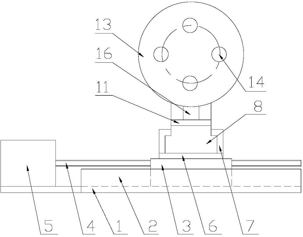
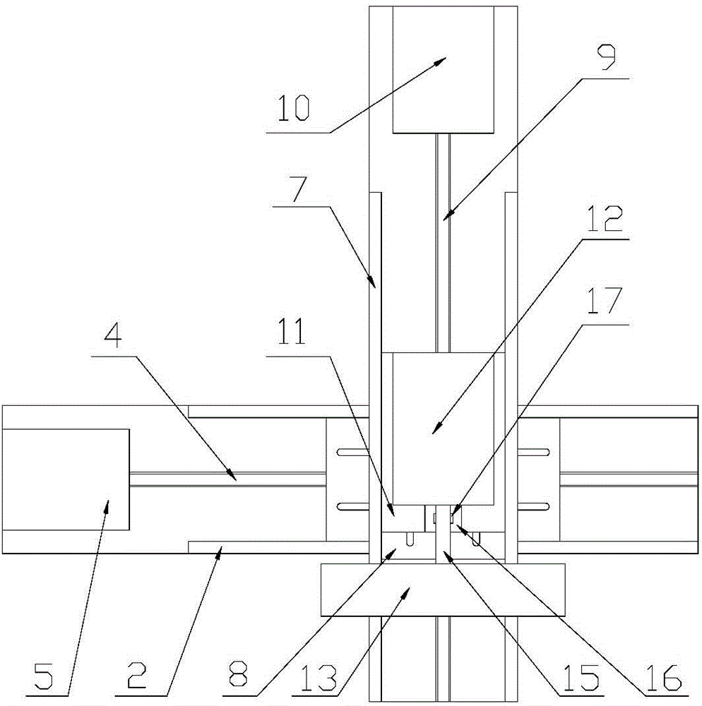
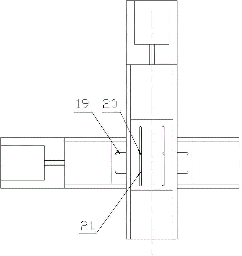
[0020] see Figure 1 to Figure 3 , is a kind of clamping device of numerical control machine tool, comprises the first base 1 that is used to be arranged on the workbench of numerical control machine tool and is rectangular plate structure, is provided with two mutually parallel first guide rails 2 on the first base 1, The first guide rail is welded and fixed on the first base 1 . The two first guide rails 2 are parallel to the two long sides of the first base 1, and the first moving plate 3 is slidably matched between the two first guide rails 2, and the inner thread of the first moving plate 3 is fitted parallel to the first The first threaded mandrel 4 of the guide rail 2 forms a first threaded mandrel nut mechanism, and the first threaded mandrel 4 is fixedly connected with the rotating shaft of the first driving motor 5 fixed on the first base 1 .

[0021] The second base 6 of rectangular plate-like structure is fixed on the first moving plate 3, the second base 6 is per...


PUM


Abstract

The invention discloses a clamping device of a numerical control machine tool. The clamping device of the numerical control machine tool is larger in moving range, capable of clamping multiple workpieces at a time and performing machining in turn, and higher in working efficiency. The clamping device comprises a first base, a first moving plate is arranged on the first base in a sliding fit manner, a first lead screw is arranged in the first moving plate in a thread fit manner, and the first lead screw is connected with a first driving motor on the first base; a second base is fixed to the first moving plate, a second moving plate is arranged on the second base in a sliding fit manner, and a second lead screw is arranged in the second moving plate in a thread fit manner; the second lead screw is connected with a second driving motor on the second base, a mounting seat is arranged on the second moving plate, and the mounting seat is longitudinally parallel to a second guide rail; a third driving motor is arranged on the mounting seat, and a rotating disc is fixed to a rotating shaft of the third driving motor; four clamps are arranged on the rotating disc, and a square is formed by the four clamps; and the crossing point of the diagonal lines of the square is located on the axis line of the first driving motor.

Description

technical field [0001] The invention relates to the field of numerically controlled machine tools, in particular to a clamping device for numerically controlled machine tools. Background technique [0002] At present, when a workpiece is processed on a CNC machine tool, a single part is fixed on the workbench. After the CNC machine tool completes the structure of the workpiece, it is necessary to replace the next workpiece and clamp it again, and then process the next workpiece, which cannot be realized. Multiple workpieces are clamped at one time and processed in turn. The work efficiency is low, which increases the production cost of the factory. On the other hand, the existing CNC machine tool has a low degree of freedom of the fixture, and cannot move in a large range on the workbench of the CNC machine tool, and there are processing blind spots. Contents of the invention [0003] The purpose of the present invention is to overcome the disadvantages of the prior art a...

Claims


Application Information

Patent Timeline
IPC IPC(8): B23Q3/06B23Q16/02B23Q7/00B23B31/40
Inventor 向小波
Owner 重庆丰德数控机床有限公司
Why Eureka
Try Eureka