Cutter head spindle spring positioning device

A technology of spring positioning and milling head, which is applied in the direction of positioning device, clamping, support, etc., can solve the problems of inability to connect, damage keys, etc., and achieve the effect of simple structure

Inactive Publication Date: 2016-07-20
WUHAN HEAVY MACHINE TOOL GRP
View PDF5 Cites 2 Cited by
  • Summary
  • Abstract
  • Description
  • Claims
  • Application Information

AI Technical Summary

Problems solved by technology

However, when installing the accessory for the second time, if there is no positioning device, the keyway on the acce

Method used


Image

  • Cutter head spindle spring positioning device
  • Cutter head spindle spring positioning device
  • Cutter head spindle spring positioning device

Examples


Embodiment Construction

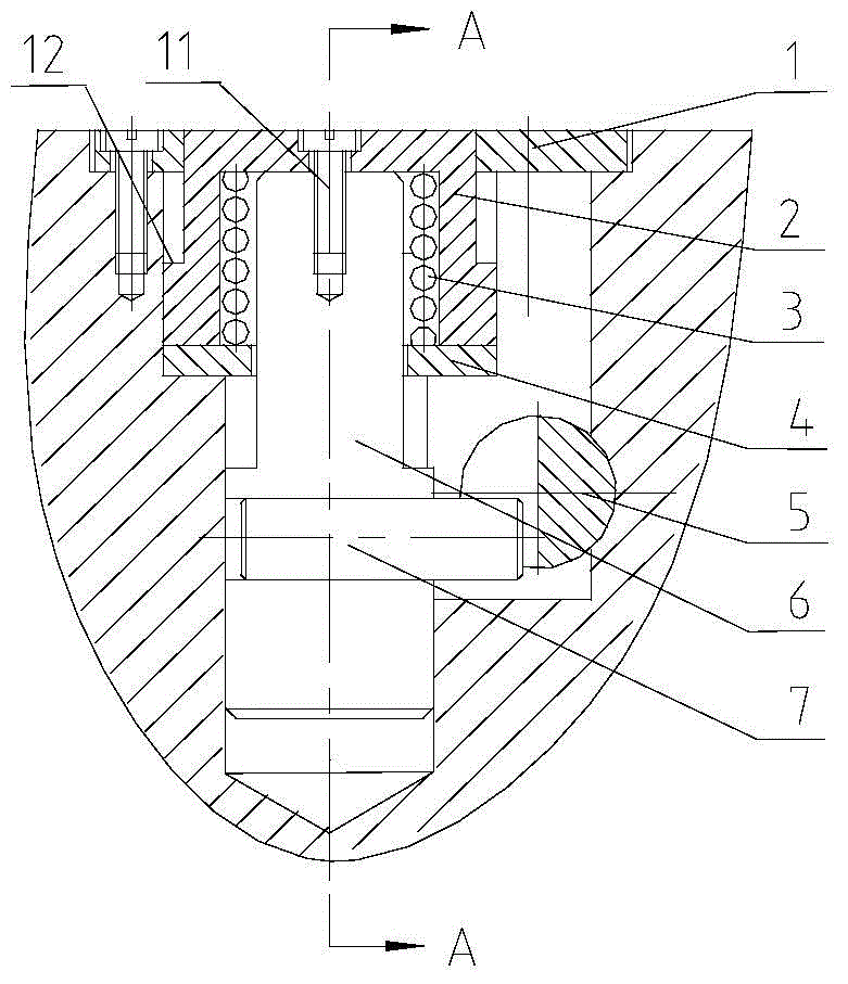
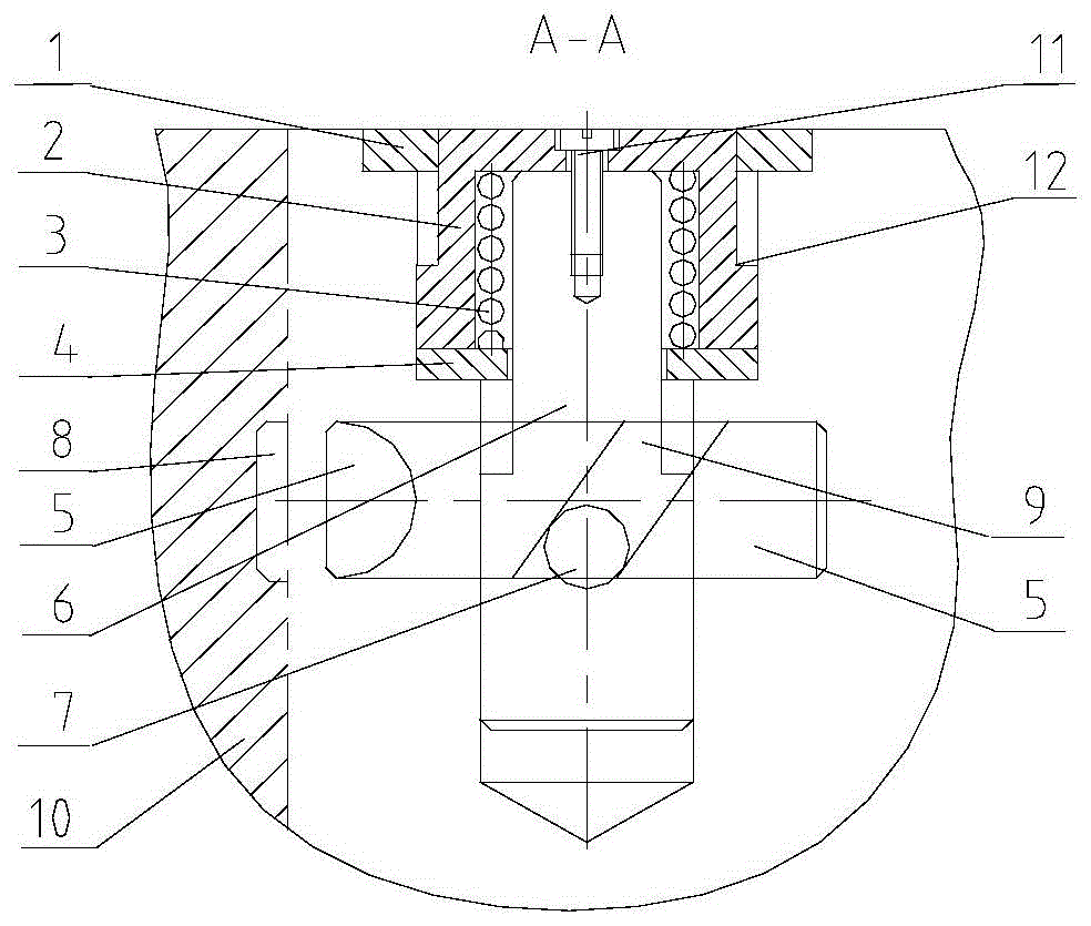
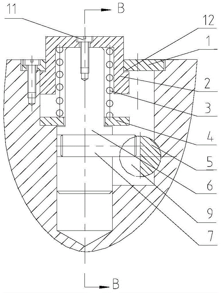
[0013] The milling spindle spindle spring positioning device mentioned in the present invention is placed in the accessory, the ejector rod 6 is placed in the pressure sleeve 2 and fixed together by the fastener 11, and the backing plate 4 fixes the spring 3 on the shaft of the ejector rod 6 and the pressure sleeve 2, a part of the pin 7 is arranged at the lower end of the push rod 6, and the other part of the pin 7 is inserted in the chute 9 provided on the latch 5. The gland 1 is arranged on the end face of the milling head attachment, and cooperates with the limit mechanism 12 provided on the pressure sleeve 2, and the entire positioning device is limited by the gland 1.

[0014] When the accessory is released from the ram, since the spring 3 is in a relaxed state, the pressure sleeve 2 and the push rod 6 are lifted up, and the pin 7 on the push rod 6 drives the latch 5 to move to the left (such as Figure 4 shown). Because the main shaft of the ram has a positioning funct...


PUM


Abstract

The invention relates to a cutter head spindle positioning device. The cutter head spindle positioning device is arranged in a cutter head accessory and comprises a pressing sleeve, a pressing cover, a base plate, an ejection rod, a bolt, a pin and a spring. The ejection rod and the pressing sleeve are fixed through a fastener. The base plate is arranged on the lower portion of the pressing sleeve. A limiting mechanism matched with the pressing cover is arranged on the pressing sleeve. The pressing cover is arranged on the end face of the cutter head accessory. The spring is arranged between the ejection rod and the pressing sleeve. One end of the pin is arranged on the ejection rod, and the other end of the pin is inserted into a bolt taper slot. When the accessory is in a working state, a ram applies pressure to the end face of the pressing sleeve when the accessory is taken, the pin located in the bolt taper slot drives the bolt to move to be away from a center shaft, and rotation of the center shaft is not influenced. When the accessory is in a non-working state, the pressing sleeve and the ejection rod are jacked, and the pin drives the bolt to extend to insert into the center shaft of the accessory, so that the center shaft is immovable, a key on the center shaft does not deviate, and the end face key of the center shaft can be accurately matched with a key slot of the accessory. The positioning device provided by the invention has the advantages of being simple and compact in structure, convenient to use and reliable.

Description

technical field [0001] The invention belongs to a milling head spindle positioning device of a vertical milling and turning compound machining center, mainly relates to the automatic and accurate positioning of the milling head attachment of the vertical milling and turning compound machining center in the process of repeated use, and is especially suitable for various vertical milling and turning compound processing Center machine tool. Background technique [0002] In the prior art, the automatic broaching method of the ram spindle of the vertical milling and turning compound machining center is that the disc spring is tensioned, the oil pressure is released, and the torque is transmitted by the plane key. But when the accessory is installed for the second time, if there is no positioning device, the keyway on the accessory and the key on the end face of the ram may be unable to connect due to misalignment, or even damage the key. Large-scale vertical milling and turning ...

Claims


Application Information

Patent Timeline
IPC IPC(8): B23Q3/157
Inventor 桂林袁利亚赵明
Owner WUHAN HEAVY MACHINE TOOL GRP
Why Eureka
Try Eureka