
Fabrication Mold of Circular Layer Structure with Lattice Features

A ring-shaped, layer-structured technology, applied in the directions of lamination, lamination device, layered products, etc., can solve the problems such as no mold for preparing a ring-shaped sandwich structure, low yield, and inconsistent specifications of finished parts. , to achieve the effect of high yield, improved production efficiency and favorable mass production

Active Publication Date: 2018-01-16
HARBIN UNIV OF SCI & TECH
View PDF5 Cites 0 Cited by
  • Summary
  • Abstract
  • Description
  • Claims
  • Application Information

AI Technical Summary

Problems solved by technology

[0003] The purpose of the present invention is to solve the problem that the products made by the existing sandwich preparation method are not uniform in size and the yield rate is low, and there is no mold for preparing the annular sandwich structure, and to propose a lattice feature Preparation of the mold for the ring-shaped layer structure

Method used


Image

  • Fabrication Mold of Circular Layer Structure with Lattice Features
  • Fabrication Mold of Circular Layer Structure with Lattice Features
  • Fabrication Mold of Circular Layer Structure with Lattice Features

Examples


specific Embodiment approach 1

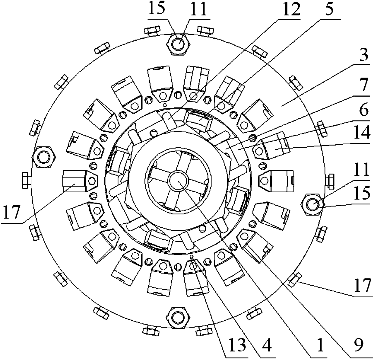
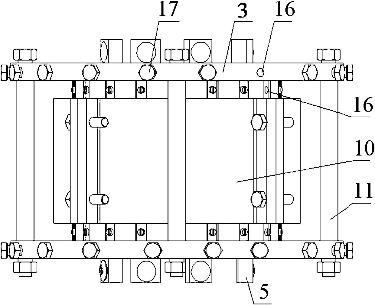
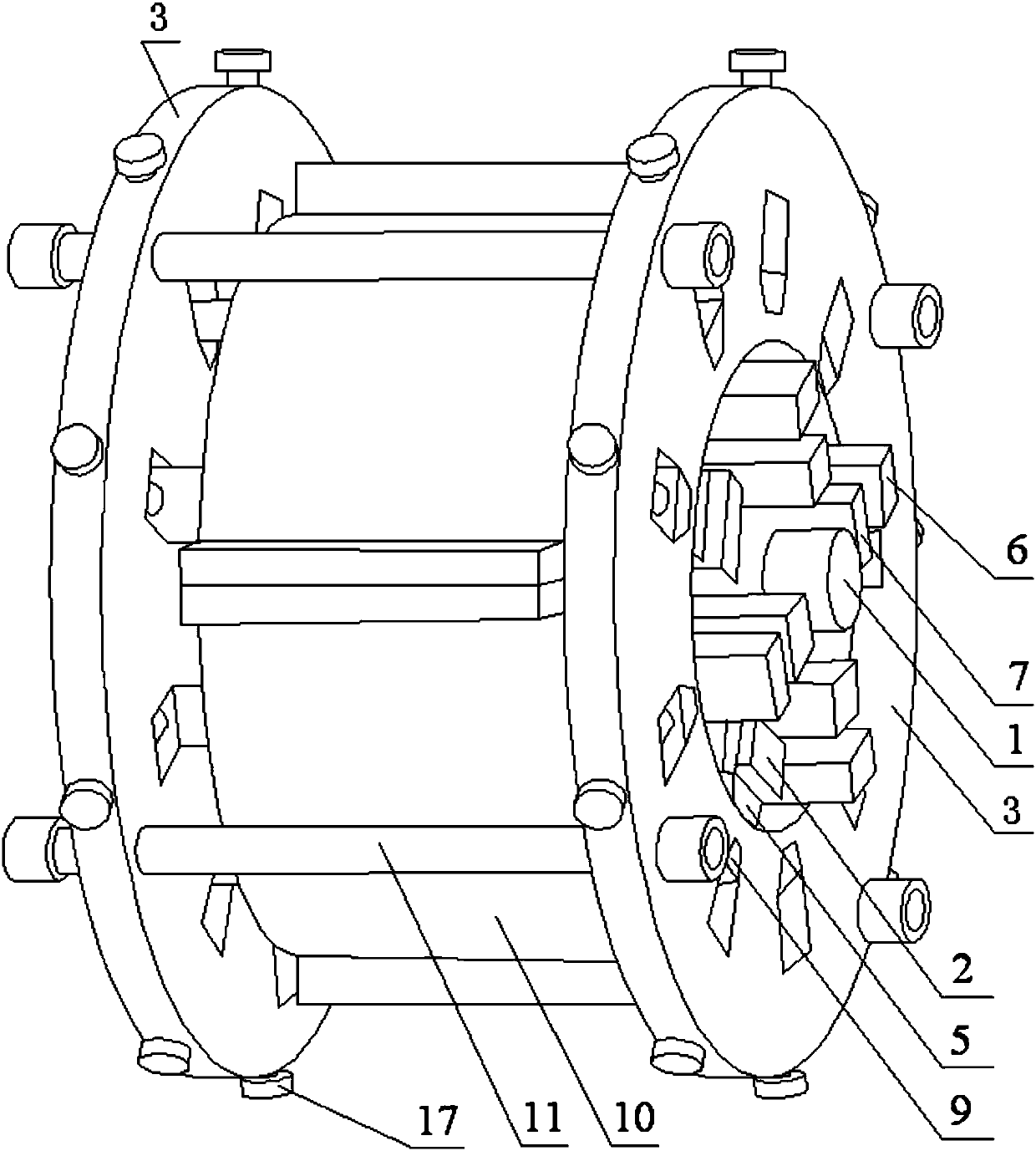
[0025] The ring-shaped layer structure with lattice characteristics of the present embodiment prepares the mould, combined with figure 1 As shown, a preparation mold with a ring-shaped layer structure with lattice characteristics, its composition includes a mandrel 1, two reducing shaft brackets 2, a group of reducing bearing pads 5, a group of reducing shaft beading 6, a A set of pads 7, a set of inner bead 8, a set of outer bead 9, a set of outer plate cylinder components 10, a set of support rods 11 and a set of adjusting screw 20;

[0026] Between the two reducer shaft brackets 2: with the mandrel 1 as the center, it includes a cylindrical layer surrounded by a set of reducer bearing pad plates 5 and a set of reducer shaft beading bars 6 arranged alternately from the inside to the outside, consisting of a set of inner A cylindrical layer surrounded by layers of beading 8 arranged in sequence, a cylindrical layer formed by a group of outer beading bars 9 arranged in sequenc...

specific Embodiment approach 2

[0030] The difference from Embodiment 1 is that in this embodiment, the ring-shaped layer structure with lattice characteristics is used to prepare the mould, each of the variable-diameter shaft brackets 2 is a ring-shaped panel, and there is a set of limit positions around the variable-diameter shaft bracket 2 plate 12, a first spacer lattice and a second spacer lattice are respectively formed between each spacer plate 12 and two adjacent spacer plates 12, and the formed first spacer lattice and second spacer lattice are Arranged alternately; wherein, the two limiting plates 12 forming the first limiting grid are arranged in parallel, and the angle between the extension lines of the two limiting plates 12 forming the second limiting grid is 90°.

specific Embodiment approach 3

[0031] The difference from Embodiment 1 or Embodiment 2 is that in this embodiment, the ring-shaped layer structure with lattice characteristics is used to prepare the mould, each of the outer bead support plates 3 is a ring-shaped panel, and the panel of the ring-shaped panel extends from the center to the surrounding area. Two positioning pin holes 13, a circle of bead holes 14 and a circle of support rod holes 15 are provided in sequence, each bead hole 14 communicates with a pressure hole 16 pointing to the center of the outer bead support plate 3, and the pressure hole 16 is screwed with an adjusting screw 20. Rotate the adjusting screw 20 to pressurize the outer bead 9 inserted in the bead hole 14 for fine adjustment.


PUM


Abstract

The invention relates to an annular sandwich layer structure production die with a dot matrix feature, belongs to the field of sandwich layer structure machining and aims to solve the problems that products produced by existing sandwich layer production methods are not unified in finished-product specification and low in yield and no dies for producing the annular sandwich layer structure exist. The annular sandwich layer structure production die with the dot matrix feature is characterized in that a mandrel (1) is a central fixing shaft, and the circumferential direction of the mandrel (1) us sequentially provided with a cylinder layer formed by a group of variable-diameter bearing bush plates (5), a cylinder layer formed a group of inner pressing strips (8), a cylinder layer formed by a group of outer pressing strips (9) and an outer pressing plate cylinder formed by sequentially-connected outer pressing plate cylinder components (10) from inside to outside by the aid of variable-diameter shaft supports (2), outer pressing strip bearing plates (3), inner pressing strip demounting plates (4) and inner pressing strip bearing rings (4); the cylinder layer formed by the inner pressing strips (8) and the outer pressing strips (9) form annular corrugated sandwich layers. The annular sandwich layer structure production die is fast in production and high in yield.

Description

technical field [0001] The invention relates to a mold for preparing an annular layer structure with lattice features. Background technique [0002] The manufacturing process of molds used in the production of traditional sandwich structure products is to make mold panels and mold cores separately, and then paste the two to form structural parts, or use sewing technology and manual sewing to make molds. The manufacturing process of these interlayer molds There are troubles, the core rod is easy to twist, the production efficiency is low, the specifications of the finished parts are not uniform, and the pasted mold is easy to open the glue, resulting in low yield. And it lacks the preparation mold for making the circular sandwich structure. Contents of the invention [0003] The purpose of the present invention is to solve the problem that the products made by the existing sandwich preparation method are not uniform in size and the yield rate is low, and there is no mold f...

Claims


Application Information

Patent Timeline
Patent Type & Authority Patents(China)
IPC IPC(8): B32B1/08B32B3/28B32B37/00
CPCB32B1/08B32B3/28B32B37/0046
Inventor 曾涛成夙楚云龙翟军军
Owner HARBIN UNIV OF SCI & TECH
Learn More