Pressure regulating type waste water ratio

A waste water ratio and pressure regulating technology, applied in the direction of osmosis/dialysis water/sewage treatment, functional valve type, reverse osmosis, etc., can solve the problem that the working pressure of the RO membrane is difficult to stabilize, can not reach a constant or adjust the outlet pressure, and the RO membrane ruptures Ineffective water production and other issues, to achieve the effect of uniform production process and low defective rate

Inactive Publication Date: 2011-06-01
蔡应麟 +1
View PDF0 Cites 0 Cited by
  • Summary
  • Abstract
  • Description
  • Claims
  • Application Information

AI Technical Summary

Problems solved by technology

The traditional RO pure water machine technology cannot achieve constant or adjustable water pressure indicators. The actual working pressure of the RO membrane is difficult to stabilize. During use, the pressure is too high to cause the failure of the RO membrane or the phenomenon that the pressure is too low and the water yield is low.

Method used


Image

  • Pressure regulating type waste water ratio
  • Pressure regulating type waste water ratio
  • Pressure regulating type waste water ratio

Examples


Embodiment 1

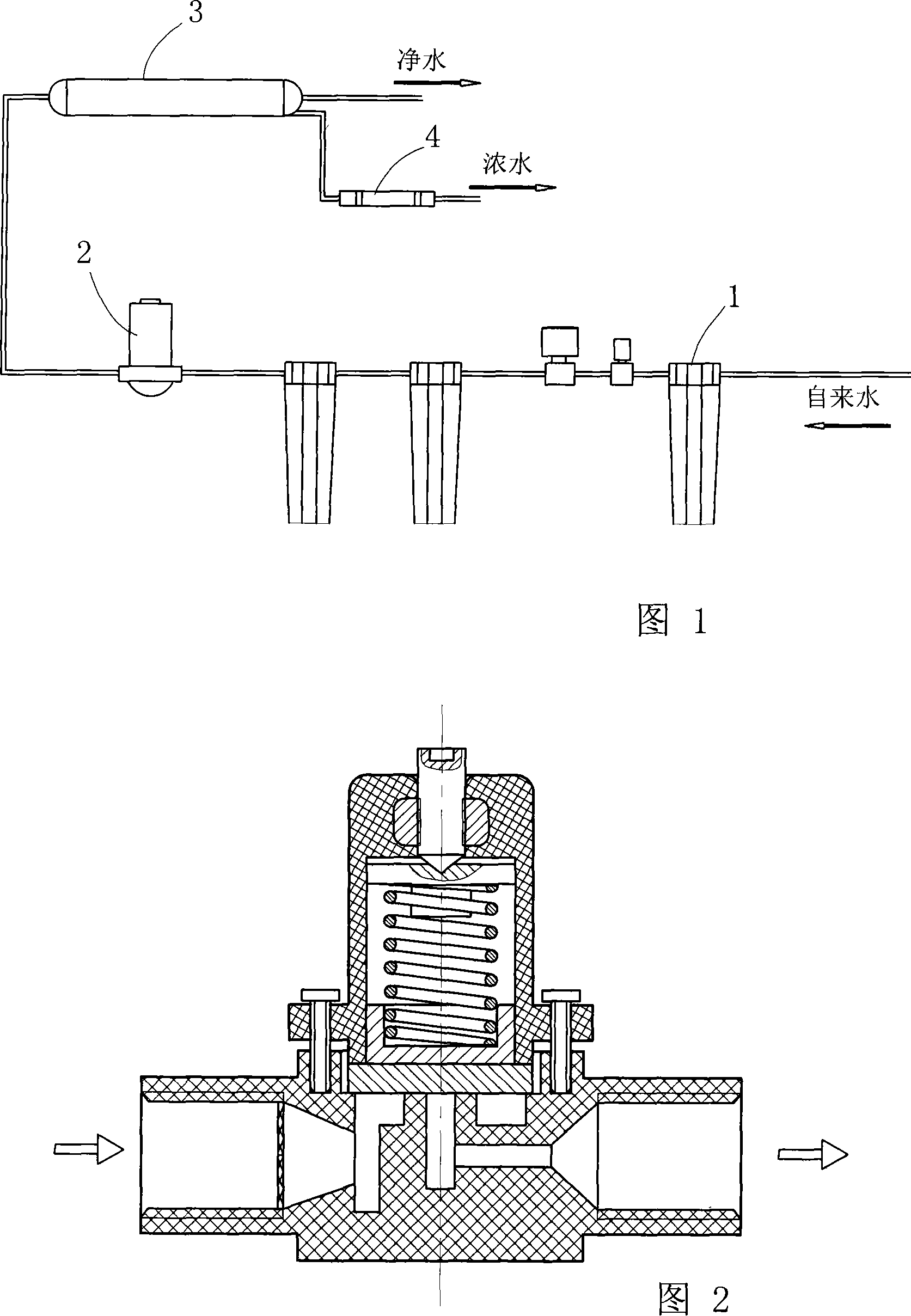
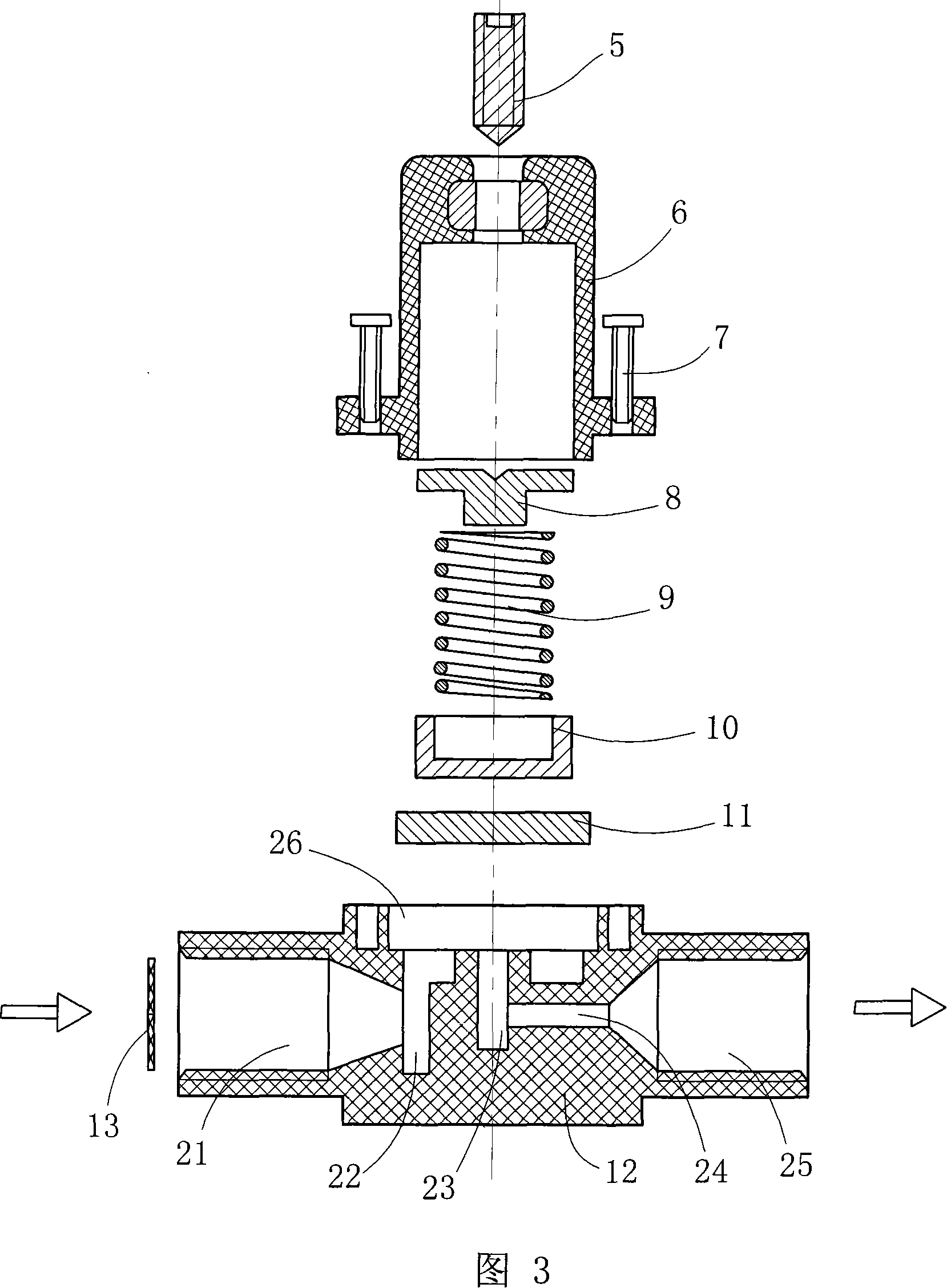
[0017] Refer to Figure 2 and Figure 3. The waste water ratio of the present invention comprises a main valve body 12 provided with inlet and outlet ports 21, 25, a pressure regulating chamber 26 is also provided on the top of the main valve body, and the end of the water inlet 21 is in the shape of a closed mouth, which communicates with the water inlet chamber 22 , the top of the water inlet chamber 22 leads to the pressure regulating chamber 26, the center of the bottom of the pressure regulating chamber 26 sinks into a small-diameter central chamber 23, the lower part of the central chamber is connected to the side water outlet chamber 24, and the end of the water outlet chamber 24 is trumpet-shaped Lead to water outlet 25.

[0018] The pressure regulating assembly is hermetically installed on the pressure regulating chamber 26 and fixed on the main valve body 12 through the screw rod 7 . The pressure regulating assembly includes a valve sleeve 6 and an elastic push block ...

Embodiment 2

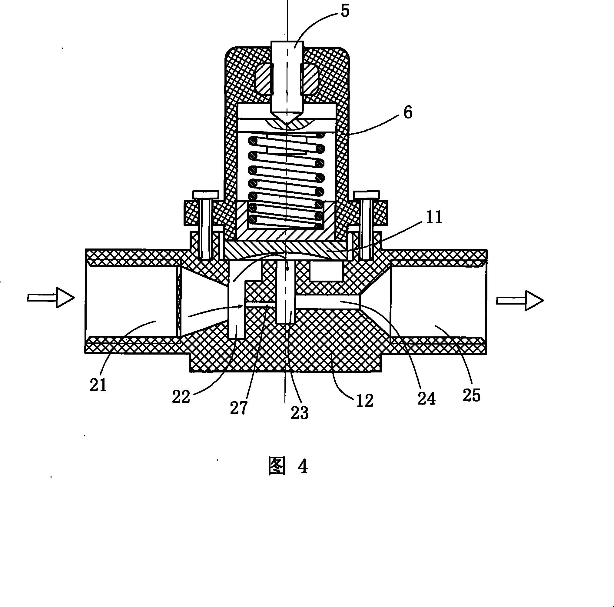
[0021] Refer to Figure 4. Between the water inlet chamber 22 and the central chamber 23 of the main valve body, a pinhole channel 27 is provided. When the working pressure of the RO pure water machine is normal, the concentrated water discharged from the RO membrane tube first passes through the pinhole channel 27; when there is an abnormality in the water network at the work site, the working pressure of the RO pure water machine is too high, and the pressure of the RO membrane tube is too high , the pressure limiting device of the present invention also plays the role of pressure limiting and pressure relief, and the increase of pinhole channels can effectively increase the flow rate of concentrated water, so that the present invention can be applied to various medium and large pure water equipment.


PUM


Abstract

The invention discloses a wastewater ratio of pressure-adjustable type, which comprises a main value body (12) which is provided with a water inlet and a water outlet (21, 25), and a regulating chamber (26). The water inlet and water outlet are communicated through the regulating chamber. A pressure regulating component is mounted on the regulating chamber. The pressure regulating components comprise a value sleeve (6) and an elastic pulling block. Screws are arranged on the top of the value sleeve. The screw extends into the value sleeve and resists the elastic pulling block. The bottom of the elastic pulling block is provided with a sealed pad (11) for dealing and blocking the regulating chamber. The invention with a matched parameter is arranged on an RO prettified water machine and the pressure limitation force by adjusting the depth of the screw on the top. When being used, particularly, the changes generated by water net pressure or the output water pressure of a booster pump isbigger than the working pressure of the PO filming pipe, the high-handed compressed water which is over the pressure limited value opens the sealed chamber of the regulating chamber from the top of the water inlet chamber on the invented main value body, thus the water entering channel is run-trough. The water is drained from the water outlet and the pressure is automatically reduced.

Description

technical field [0001] The invention relates to the wastewater ratio in pure water equipment, in particular to a wastewater ratio with adjustable pressure. Background technique [0002] Among water appliances that use reverse osmosis technology for water purification, the pure water machine is a small factory that produces pure water. As shown in Figure 1, the purification system mainly includes activated carbon filter 1 (filter element I, filter element II, filter element III), booster pump 2, reverse osmosis membrane tube (RO membrane tube) 3 and waste water ratio 4 and other components. Since the pore size of the RO membrane in the RO membrane tube is only 0.0001-0.001 microns, most of the inorganic salts (including heavy metals), organic matter, bacteria, and viruses dissolved in water cannot pass through the RO membrane. As the core RO membrane tube, with the help of the pressurization of the booster pump at the front end of the RO membrane tube and the back pressure o...

Claims


Application Information

Patent Timeline
Patent Type & Authority Patents(China)
IPC IPC(8): B01D61/10F16K17/06F16K17/04C02F1/44
Inventor 徐兆火蔡应麟
Owner 蔡应麟
Why Eureka
Try Eureka