T-shirt printing system adopting rotary bracket and cantilever beam spray printing device and T-shirt printing method

A printing method and cantilever beam technology, applied in the direction of rotary printing machine, printing, printing machine, etc., can solve the problem of low work efficiency of the clothing printing method and clothing printing system, insufficient color display and printing fineness, low printing efficiency, etc. problems, to achieve the effect of high equipment utilization, convenient maintenance and flexible use

Inactive Publication Date: 2016-07-20
HANGZHOU HONGHUA DIGITAL TECH
View PDF13 Cites 6 Cited by
  • Summary
  • Abstract
  • Description
  • Claims
  • Application Information

AI Technical Summary

Problems solved by technology

[0002] At present, the existing T-shirt printing system generally includes the following structures: one is the octopus T-shirt printing machine and the oval printing machine, which adopts the rotary bracket and the matching screen printing machine to be located on the pallet. T-shirts are printed over-color, so usually at least four times of over-color printing are required to complete the printing of a T-shirt. This method of traditional screen printing requires the production of screens, and the production cost is relatively high. Therefore, it is more suitable for the production of single-piece large-volume orders, and because it is traditional printing, printing effects such as color display and printing fineness are obviously insufficient compared with digital printing, especially when personalized small-batch printing costs too much high
The other is a T-shirt printing machine that uses digital printing. It uses a digital printing device with a door-shaped structure that is common on the market, and a T-shirt pallet that can move relative to the beam under the door-shaped beam. The top suit T-shirt is similar to the structure of a flatbed printing machine, the only difference is that the printing flatbed is replaced by a special T-shirt pallet, but when the T-shirt is loaded and removed during the printing process, the printing device is in a non-working state , so the printing efficiency is relatively low
[0003] For example, the publication date is November 25, 2009, and the publication number is CN101589190 in the Chinese patent, which discloses a clothing printing method and a clothing printing system using an inkjet printer. T-shirt stretcher, the T-shirt stretcher is opened left and right, the waist part of the T-shirt is opened left and right, thereby the front surface part and the back part of the waist part are stretched into a flat state (clothes stretching process), and then The T-shirt opened left and right by the T-shirt stretcher is placed on the medium loading table of the inkjet printer with the front surface facing up (clothes setting process), and then the inkjet printer is driven to print the printed image on the T-shirt. At the set position of the front surface part of the waist part of the shirt, the pattern can be printed on the T-shirt beautifully using an inkjet printer, but the work efficiency of the clothing printing method and clothing printing system is still low.
[0004] To sum up, there is currently no T-shirt printing system and T-shirt printing system with a rotary bracket and a cantilever beam printing device that has a reasonable structural design, flexible use, and can greatly improve the efficiency and quality of T-shirt printing. method

Method used


Image

  • T-shirt printing system adopting rotary bracket and cantilever beam spray printing device and T-shirt printing method
  • T-shirt printing system adopting rotary bracket and cantilever beam spray printing device and T-shirt printing method
  • T-shirt printing system adopting rotary bracket and cantilever beam spray printing device and T-shirt printing method

Examples


Embodiment Construction

[0038] The present invention will be further described in detail below in conjunction with the accompanying drawings and examples. The following examples are explanations of the present invention and the present invention is not limited to the following examples.

[0039] Example.

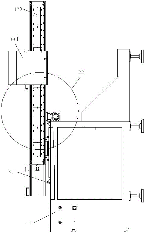
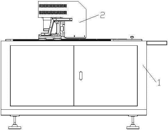
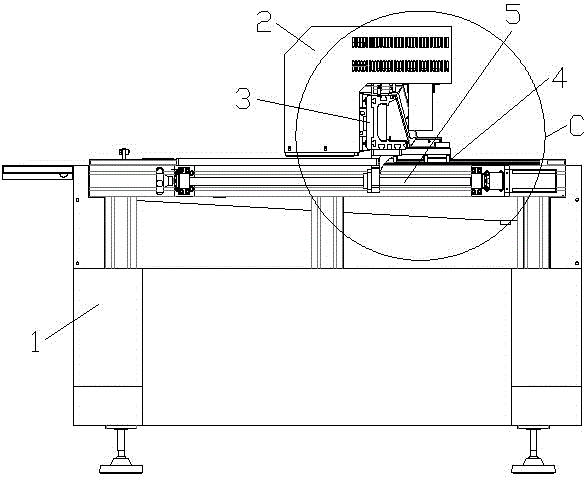
[0040] see Figure 1 to Figure 16 , The T-shirt printing system in this embodiment includes a rotary bracket I and a cantilever beam printing device II. The rotary bracket I is provided with several T-shirt pallets 6 that can rotate with the rotary bracket I.

[0041] The cantilever beam printing device II in this embodiment includes a printing device frame 1, a printing mechanism 2 and a cantilever beam 3, and one end M of the cantilever beam 3 is installed on the printing device frame 1 through a group of cantilever guide rail assemblies 4. On the other hand, the other end N of the cantilever beam 3 forms a cantilever structure directly overhead on the side of the printing device frame 1 facing ...


PUM


Abstract

The invention relates to a T-shirt printing system adopting a rotary bracket and a cantilever beam spray printing device and a T-shirt printing method. At present, the T-shirt printing system adopting the rotary bracket and the cantilever beam spray printing device and the T-shirt printing method by which the T-shirt printing efficiency and the T-shirt printing quality can be greatly improved have not been invented. The T-shirt printing system comprises the rotary bracket; and a plurality of T-shirt supporting plates which can rotate along with the rotary bracket are arranged on the rotary bracket. The T-shirt printing system is characterized by further comprising the cantilever beam spray printing device; the cantilever beam spray printing device comprises a spray printing device rack, a printing mechanism and a cantilever beam; and one end of the cantilever beam is arranged on the spray printing device rack through a group of cantilever beam guide rail components, and an outrigger structure is formed at the other end of the cantilever beam and is directly erected at one side, facing the T-shirt supporting plates, of the spray printing device rack, so that actual printing areas of the T-shirt supporting plates are positioned in a printing area of the cantilever beam spray printing device. According to the T-shirt printing system and the T-shirt printing method disclosed by the invention, the T-shirt printing efficiency and the T-shirt printing quality can be greatly improved.

Description

technical field [0001] The invention relates to a T-shirt printing system and a T-shirt printing method, in particular to a T-shirt printing system and a T-shirt printing method using a rotary bracket and a cantilever beam spray printing device, which are specially used for T-shirt printing. Background technique [0002] At present, the existing T-shirt printing system generally includes the following structures: one is the octopus T-shirt printing machine and the oval printing machine, which adopts the rotary bracket and the matching screen printing machine to be located on the pallet. T-shirts are printed over-color, so usually at least four times of over-color printing are required to complete the printing of a T-shirt. This method of traditional screen printing requires the production of screens, and the production cost is relatively high. Therefore, it is more suitable for the production of single-piece large-volume orders, and because it is traditional printing, printi...

Claims


Application Information

Patent Timeline
Patent Type & Authority Applications(China)
IPC IPC(8): B41F19/00B41F15/08
CPCB41F15/08B41F19/007B41J3/4078
Inventor 谢伟华卢明杰徐全伟孙蔚
Owner HANGZHOU HONGHUA DIGITAL TECH
Why Eureka
Try Eureka