
Optical fiber manufacturing method

A manufacturing method and optical fiber technology, applied in the field of optical fiber manufacturing, can solve problems such as complex procedures, low processing efficiency, and long time consumption, and achieve the effect of simplifying the process and improving processing efficiency

Active Publication Date: 2018-03-09
HANGZHOU FUTONG COMM TECH CO LTD
View PDF4 Cites 0 Cited by
  • Summary
  • Abstract
  • Description
  • Claims
  • Application Information

AI Technical Summary

Problems solved by technology

It solves the problems of complex process, long time-consuming and low processing efficiency caused by welding two auxiliary rods first and then fusing one auxiliary rod in the existing manufacturing method

Method used

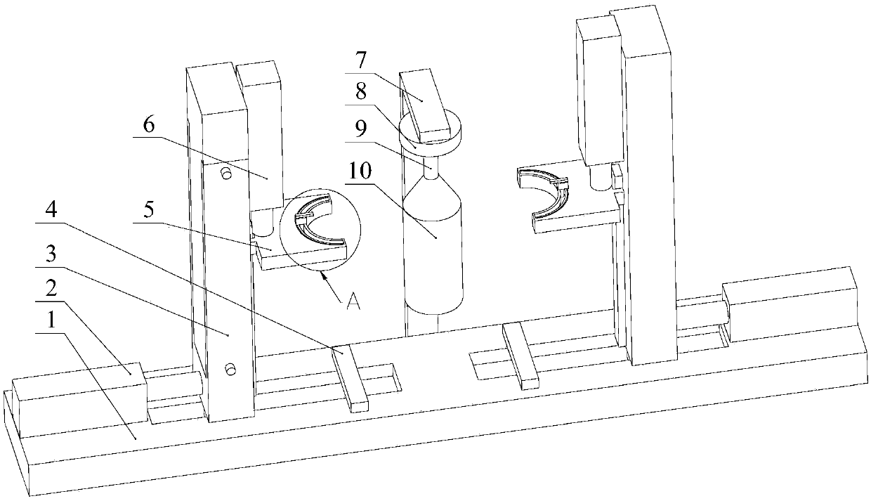
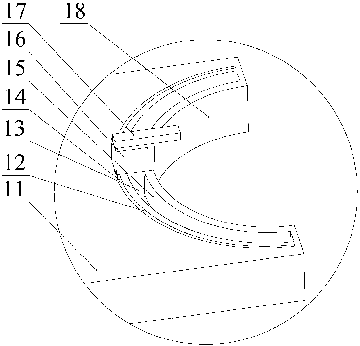

Image

  • Optical fiber manufacturing method
  • Optical fiber manufacturing method
  • Optical fiber manufacturing method

Examples


Embodiment Construction

[0037] Below in conjunction with each accompanying drawing, the present invention is described in detail.

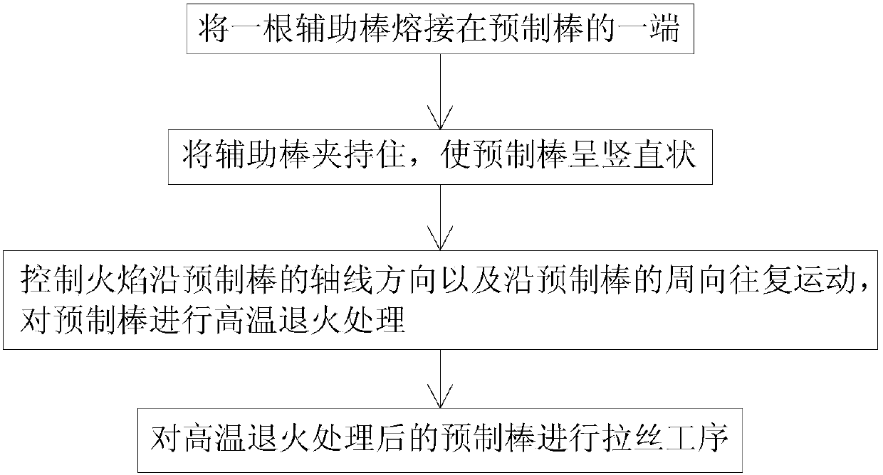
[0038] Such as figure 1 As shown, this embodiment discloses a method for manufacturing an optical fiber, comprising the following steps:

[0039] 1) An auxiliary rod is welded to one end of the prefabricated rod;

[0040] 2) Clamp the auxiliary rod so that the preform is vertical;

[0041] 3) Controlling the reciprocating movement of the flame along the axial direction of the preform rod and along the circumferential direction of the preform rod, and performing high-temperature annealing treatment on the preform rod;

[0042] 4) A wire drawing process is performed on the preform after the high-temperature annealing treatment.

[0043] In the existing manufacturing method, two chucks drive the preform to rotate, and then the blowtorch only needs to reciprocate along the axial direction of the preform to perform high-temperature annealing treatment. Compared with the e...


PUM


Abstract

The invention discloses a production method of an optical fiber. The production method comprises the following steps: 1) welding an auxiliary rod at one end of a preform; 2) clamping the auxiliary rod so that the preform is vertical; 3) controlling the flame to reciprocate along the axis direction of the preform and the circumferential direction of the preform, and performing high-temperature annealing treatment on the preform; and 4) performing a wiredrawing process on the preform after the high-temperature annealing treatment. Compared with existing production methods, in the invention, high-temperature annealing treatment is performed on the preform by controlling the flame to reciprocate along the axis direction of the preform and the circumferential direction of the preform, the preform is not clamped by two chucks, and only one auxiliary rod is welded; and by adopting the production method disclosed by the invention, the technological process is effectively simplified, and the processing efficiency is improved.

Description

technical field [0001] The invention relates to the field of optical fibers, in particular to a method for manufacturing optical fibers. Background technique [0002] In optical fiber manufacturing, it is necessary to flame grind the preform before the drawing process. Before the flame grinding of the preform, an auxiliary rod is welded to each end of the preform, and then the two chucks hold the corresponding auxiliary rods respectively. When the two chucks rotate at the same speed, the preform and the auxiliary rod are driven to rotate, and the preform is burned at high temperature by a movable blowtorch. The blowtorch uses hydrogen and oxygen as fuel, and generates a high temperature of about 2300°C during combustion , can remove impurities and dust on the surface of the preform, release the unevenly distributed internal stress in the preform, heal the fine cracks on the surface of the preform, and avoid fiber breakage during the wire drawing process. After flame grindin...

Claims


Application Information

Patent Timeline
Patent Type & Authority Patents(China)
IPC IPC(8): C03B37/012
CPCC03B25/00C03B37/012
Inventor 吴海港何建儿何园园郝小龙
Owner HANGZHOU FUTONG COMM TECH CO LTD
Learn More