Optic fiber prefabricated loose mass deposition device and deposition method thereof

A deposition device and deposition method technology, applied in glass deposition furnaces, manufacturing tools, glass manufacturing equipment, etc., can solve the problems of production costs and increase production efficiency, and can save gas consumption and improve production efficiency by adding blowtorches. Effect

Inactive Publication Date: 2016-07-20
HENGTONG OPTICAL MATERIAL CO LTD
View PDF3 Cites 6 Cited by
  • Summary
  • Abstract
  • Description
  • Claims
  • Application Information

AI Technical Summary

Problems solved by technology

[0009] The current space for technology to reduce production costs and improve production efficiency cannot be completed by adding blowtorches

Method used


Image

  • Optic fiber prefabricated loose mass deposition device and deposition method thereof
  • Optic fiber prefabricated loose mass deposition device and deposition method thereof

Examples


Embodiment Construction

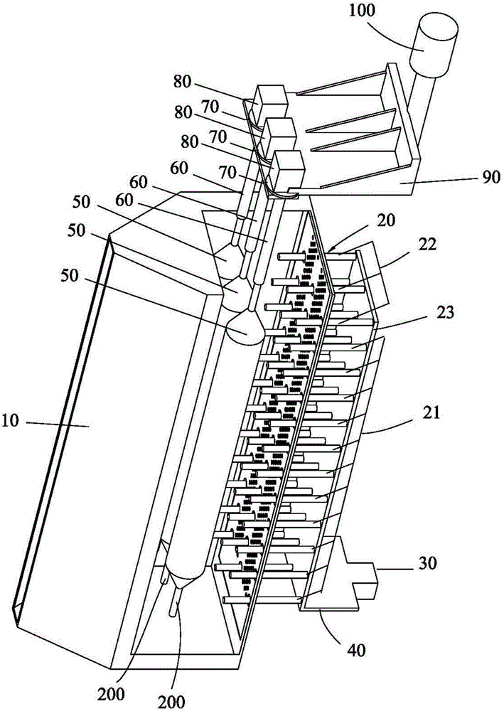
[0032] The invention provides a fiber prefabricated loose body deposition device, which can be used for SiCl 4 Hydrolytic deposition produces optical fiber prefabricated loose body or organosilicon combustion deposition produces optical fiber preformed rod loose body.

[0033] see figure 1 As shown, the deposition device includes: a box body 10, an R×C matrix distribution torch 20 fixed in the box body 10, a torch translation motor 30 connected to the R×C matrix distribution torch 20, and a torch translation platform 40, C A target rod 200, C lead rods 60 correspondingly connected to the C target rods 200, C sensors 70 correspondingly connected to the C lead rods 60, C rotating motors correspondingly connected to the C lead rods 60 80 . The elevating platform 90 for fixing the C rotating motors 80 , and the elevating motor 100 connected with the elevating platform 90 . Among them, 4≤R≤12, 1≤C≤6, R≥C; the guide rod 60 is fixed on the lifting platform 90; the sensor 70 is a we...


PUM


Abstract

The invention provides an optic fiber prefabricated loose mass deposition device and a deposition method thereof. The deposition device comprises a tank, torch lamps distributed in RXC matrix, a torch lamp translation motor, a blow lamp translation platform, C target bars, C lead rods, C sensors, C rotary motors, a lifting carrier platform, and a lifting motor. The target bars extend along the first direction and are arranged above the the first blow lamp correspondingly, and the extending direction of each target bar correspond to the first blow lamp of each row in the first direction. C loose masses can be deposited in the tank, and compared with a conventional method, 3X(C-1) servo motors can be reduced, and isolation gas inside and outside of the blow lamps in the same row in the matrix distribution can share the same mass flowmeter, so that 2XRX(C-1) mass flowmeters can be saved. The matrix distribution method of the blow lamps can greatly increase production efficiency of the device, and deposition speed is RC times of the single blow lamp.

Description

technical field [0001] The invention belongs to the technical field of optical fiber prefabricated rod manufacturing, and in particular relates to an optical fiber prefabricated loose body deposition device and a deposition method thereof. Background technique [0002] The existing optical fiber preform manufacturing method, the first step: the core rod is produced by the axial vapor deposition method (VAD), the second step is the external vapor deposition method (OVD) to produce the outer cladding, and the optical fiber prefabrication is produced by these two steps Great. As we all know, 70% of the cost of optical fiber prefabrication is determined by the cladding part, and the production cost and production efficiency of the OVD method have a great impact on the cost of the optical fiber preform. [0003] At present, the OVD method for producing loose optical fiber preforms is generally a single set of blowtorch reciprocating deposition. The number of deposition torches i...

Claims


Application Information

Patent Timeline
IPC IPC(8): C03B37/014
CPCC03B37/01406C03B2207/66C03B2207/62C03B2207/50C03B37/014Y02P40/57C03B37/0142C03B37/01493C03B2207/52C03B2207/70
Inventor 田国才肖华赵奉阔胡付俭屠建宾劳雪刚
Owner HENGTONG OPTICAL MATERIAL CO LTD
Why Eureka
Try Eureka