
Correction system and method for ballastless track bridge of high speed railway run in soft soil area

A high-speed railway and ballastless track technology, applied in the field of deviation correction system, can solve the problems of high risk, large ballastless track structure damage, short skylight time, etc., to achieve flexible and controllable operation, controllable construction quality, and broad application prospects Effect

Inactive Publication Date: 2016-07-20
中铁四院集团工程建设有限责任公司
View PDF5 Cites 8 Cited by
  • Summary
  • Abstract
  • Description
  • Claims
  • Application Information

AI Technical Summary

Problems solved by technology

However, engineering activities such as one-sided loading of bridges, excavation of foundation pits, or asymmetric construction of post-maintenance repairs may cause the lateral deformation of ballastless track bridges in soft soil areas to exceed the limit, damage the smoothness of the track structure, and cause trains to overturn in severe cases
[0003] A large number of ballastless tracks used in my country usually use longitudinal connections, which have high longitudinal and lateral rigidity and cannot be repaired in a short period of time, and the use of traditional ballasted track push, pull, and track-shifting lateral deformation correction methods will cause great damage to the ballastless track structure and risk very high
The skylight time of the high-speed railway is short, and the operation or suspension of the high-speed railway is affected by the correction of the track structure, which not only causes economic losses, but also may have a huge negative social impact
The above factors greatly restrict the selection of the correction scheme, making it almost impossible to directly correct the track structure on the bridge
At present, there is no method for rectifying ballastless track bridges of high-speed railways in soft soil areas that do not need to interrupt operations, do not damage the track structure, and have low risks

Method used


Image

  • Correction system and method for ballastless track bridge of high speed railway run in soft soil area
  • Correction system and method for ballastless track bridge of high speed railway run in soft soil area

Examples


Embodiment Construction

[0020] The present invention will be described in further detail below in conjunction with the accompanying drawings and specific embodiments:

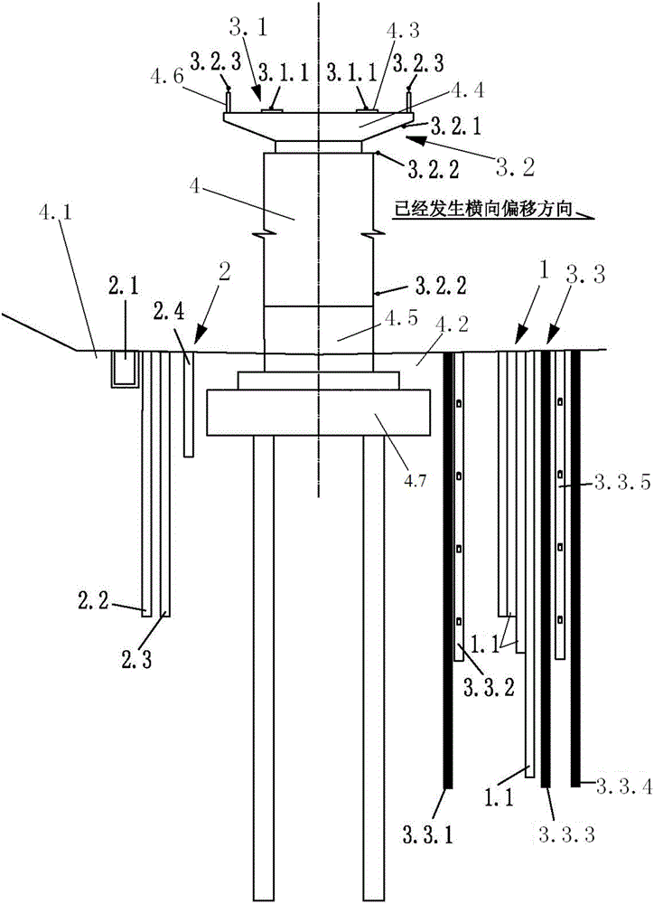
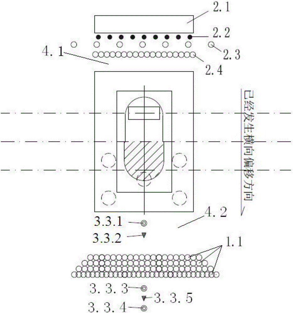
[0021] like figure 1 and figure 2 The described deviation correction system for operating high-speed railway ballastless track bridges in soft soil areas includes a force transmission system 1, a stress relief and release system 2 and a foundation deformation monitoring system 3.3. The force transmission system 1 includes multiple rows of high-pressure orientation Injection device 1.1, stress relief and release system 2 includes deformation groove 2.1, soil excavation hole group, stress relief hole group and stress relief hole group, foundation deformation monitoring system 3.3 includes first inclinometer pipe 3.3.1, second inclinometer pipe 3.3.3, the third inclinometer pipe 3.3.4, the first pore water pressure gauge 3.3.2 and the second pore water pressure gauge 3.3.5, among which, the lateral displacement of the high-speed railwa...


PUM

PropertyMeasurementUnit
Apertureaaaaaaaaaa
Apertureaaaaaaaaaa

Abstract

The invention discloses a correction system for a ballastless track bridge of a high speed railway run in a soft soil area. A deformation slot, a soil digging hole group, a stress release hole group and a stress removal hole group are sequentially formed in an asymmetrical load stacking area foundation in the transverse displacement correction direction of a high speed railway ballastless track bridge pier from the outer side to the inner side; a first inclinometer, a first pore water pressure gauge, multiple rows of high pressure directional jet devices, a second inclinometer, a second pore water pressure gauge and a third inclinometer are sequentially arranged in a transverse deviation side foundation of the high speed railway ballastless track bridge pier from the inner side to the outer side. According to the invention, the bridge is driven by the bridge pier foundation to move by exerting acting force on the bridge pier foundation, so that the purpose of correcting the transverse displacement of the bridge is realized.

Description

technical field [0001] The invention relates to the technical field of civil engineering, in particular to a deviation correction system and method for operating high-speed railway ballastless track bridges in soft soil areas. Background technique [0002] In recent years, my country's high-speed railway has developed rapidly. In order to avoid fertile land, save land, and reduce the impact of soft soil deformation on the subgrade, bridges have become the main engineering type of high-speed railway projects. The foundations of railway bridges are mainly pile-cap foundations, and this type of deep foundation is effective in controlling post-construction settlement of bridges. In terms of line tracks, ballastless tracks are widely used in high-speed railways in my country based on the advantages of long service life, good durability, and low maintenance workload. However, engineering activities such as piling on one side of the bridge, excavation of foundation pits or asymmet...

Claims


Application Information

Patent Timeline
IPC IPC(8): E02D35/00E02D1/08E01D22/00E01B35/02G01B21/32
CPCE02D35/00E01B35/02E01D22/00E02D1/08G01B21/32
Inventor 陈仕奇陈占彭志鹏孙宏林周青爽邬强孟长江李丹午师敏涂勇周勇梁龙标何新辉
Owner 中铁四院集团工程建设有限责任公司
Learn More