Horizontal blade wind power generator

A technology of wind generators and horizontal wings, which is applied to the control of wind engines, wind motor combinations, and wind engines, etc., and can solve problems such as failure to make full use of wind farm resources, aggravate wind turbine vibration, and increase wind turbine costs , to improve the start-up performance and wind energy utilization, reduce the start-up wind speed, and increase the windward area

Active Publication Date: 2016-07-20
HARBIN ENG UNIV
View PDF7 Cites 9 Cited by
  • Summary
  • Abstract
  • Description
  • Claims
  • Application Information

AI Technical Summary

Problems solved by technology

Patent ZL200820017859.3 changes the aerodynamic parameters of the wind turbine by changing the aerodynamic shape of the blade airfoil. Although the start-up performance of the vertical axis wind turbine is improved, the change of the aerodynamic shape of the airfoil affects the performance of the wind turbine at a high tip speed ratio. Power generation efficiency has a great impact, and the special blade airfoil will undoubtedly increase the cost of wind turbines
Patent 200820091137.2 "Vertical shaft semi-active semi-solid combined blade windmill", because only one blade moves, the structure seems simple, but it fails to make full use of the wind field resources of the wind turbine, and intensifies the turbulent flow between the fixed blade and the movable blade. It deteriorates the stress environment of the blades, increases the requirements for the strength and stiffness of the blades, aggravates the vibration of the wind turbine, affects the overall performance, and has poor practicability

Method used


Image

  • Horizontal blade wind power generator
  • Horizontal blade wind power generator
  • Horizontal blade wind power generator

Examples


Embodiment Construction

[0020] The present invention is described in more detail below in conjunction with accompanying drawing example:

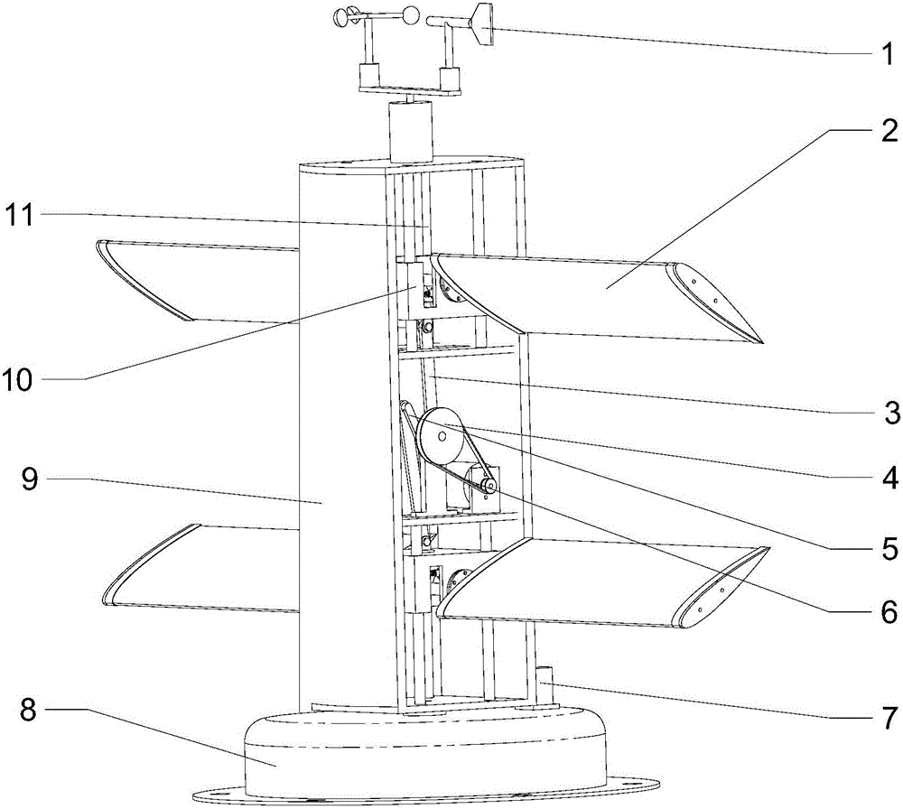
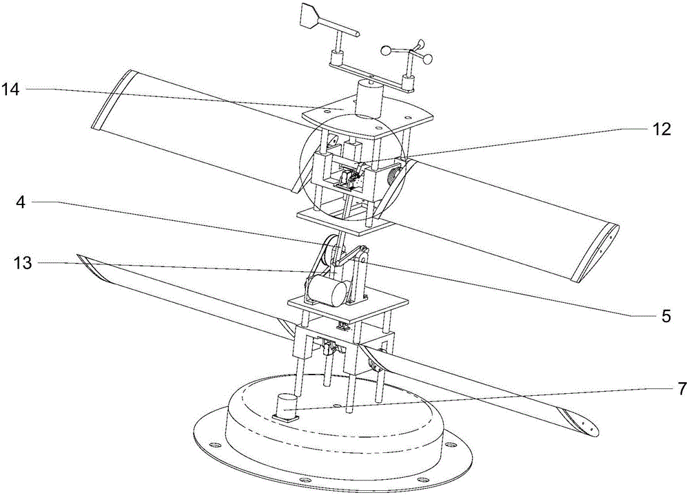
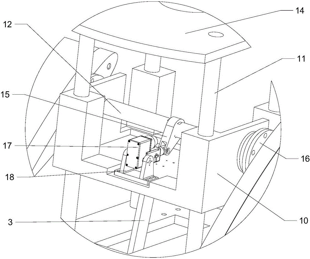
[0021] combine Figure 1~5 , the present invention is a horizontal wing wind generator, which is composed of two sets of blade mechanisms, a power generation module, a rotary module and a frame. Every group of vane mechanism comprises two vanes 2 and vane connecting rod 12 thereof, an electric cylinder 17 and base 18 thereof, large sliding seat 10, upper seat 11, cam 15, hinge seat 22 and guide rod 3 etc. are formed. Power generation module is made up of crankshaft 5, the synchronous belt speed-up mechanism that big and small pulleys and belt form and generator 24. The rotary module is composed of a detection wind force wind direction sensor 1 installed on the upper cover, a rotary motor 7 installed on the base and a synchronous belt deceleration mechanism composed of large and small pulleys. Frame comprises column 9, base 8 and loam cake 14 etc. are formed.

...


PUM


Abstract

The invention aims to provide a horizontal blade wind power generator. Two blades subjected to wind power move up and down, so that a crankshaft rotates, a crankshaft generator rotates to generate power, and an electric cylinder adjusts the angles of the blades to better face wind and bear force. The wind power generator is controlled according to the condition of a wind field and the whole wind power generator rotates to a wind facing direction so as to improve the starting capacity and the power generation efficiency of the wind power generator. Each group of blades moves independently, the angle of each blade is adjusted by the electric cylinder, and each blade driven by the wind power reciprocates up and down along a slide rail and is connected to the crankshaft through a guide rod. Two groups of blade mechanisms are symmetrically arranged up and down and commonly drive the crankshaft to rotate so as to play a gravity compensation role. A wind direction and wind speed sensor is mounted at the upper end of a frame to sense the wind direction, and the whole wind power generator is rotated through a motor at the lower end of the frame, so that the blades of the wind power generator can better face the wind and bear the force to operate. The whole wind power generator provided by the invention can be adjusted according to the wind direction, and the electric cylinder drives the blades to rotate to better wind-facing angles so as to realize a relatively high utilization rate of wind energy.

Description

technical field [0001] The invention relates to a generator, specifically a wind power generator. Background technique [0002] Wind power technology has become an effective means to solve energy shortage, environment and climate change on a global scale, and plays a major role in the development and utilization of new energy. Although there are many models of various types of wind turbines at present, the power generation performance of wind turbines needs to be improved, and the research and development and manufacturing costs of various types of wind turbines are relatively high, which is not conducive to the promotion of wind turbines. According to the spatial position of the main shaft, wind turbines can be divided into two types, vertical axis fans and horizontal axis fans. [0003] Now, there are many fans in various forms. Patent ZL200820017859.3 changes the aerodynamic parameters of the wind turbine by changing the aerodynamic shape of the blade airfoil. Although ...

Claims


Application Information

Patent Timeline
Patent Type & Authority Applications(China)
IPC IPC(8): F03D9/25F03D5/04F03D7/00F03D13/20F03D15/10
CPCF03D5/04F03D7/00F05B2260/76Y02E10/70
Inventor 张立勋谢春辉蒋延达姜锡泽马吉李国强
Owner HARBIN ENG UNIV
Why Eureka
Try Eureka