Wave beam forming method

A beam and azimuth technology, applied in the field of target detection, can solve the problem that beamforming technology cannot meet high resolution and tolerance at the same time

Active Publication Date: 2016-07-20
INST OF ACOUSTICS CHINESE ACAD OF SCI
View PDF5 Cites 7 Cited by
  • Summary
  • Abstract
  • Description
  • Claims
  • Application Information

AI Technical Summary

Problems solved by technology

[0006] The purpose of the present invention is to overcome the defect that the beamforming technology in the prior art cannot sati

Method used


Image

  • Wave beam forming method
  • Wave beam forming method
  • Wave beam forming method

Examples


Embodiment Construction

[0069] The present invention will be further described now in conjunction with accompanying drawing.

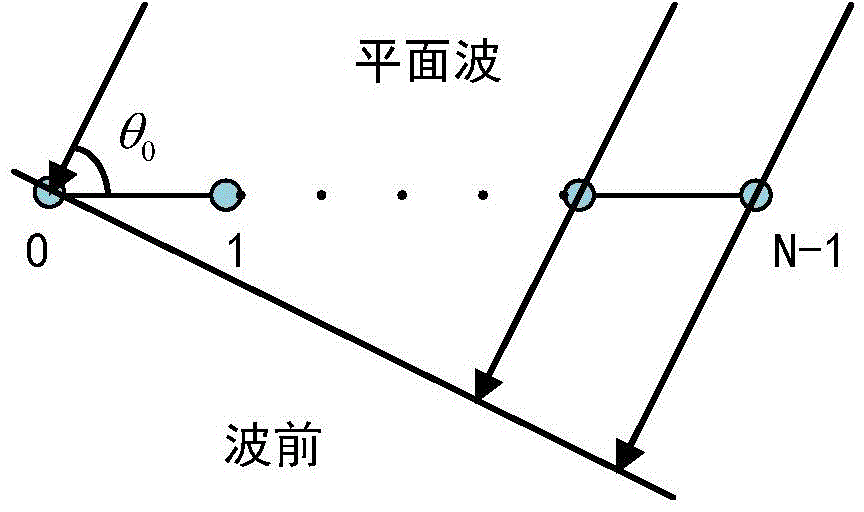
[0070] Before the method of the present invention is described in detail, the receiving array to which the method of the present invention is applicable is firstly described. figure 1 It is a schematic diagram of a receiving array, the receiving array is an equidistant horizontally dragged linear array with N array elements, and these N array elements are sequentially recorded as array elements 0, 1, 2, ..., N-1; where , the 0th array element is the reference array element. θ 0 Drag the line array radiation signal direction relative to the target horizontally.

[0071] based on figure 1 As shown in the receiving array, the beamforming method of the present invention includes:

[0072] Step 1), perform Fourier transform analysis on the data received by each array element in the receiving array, then perform phase compensation and accumulation on the results obtained by Fou...


PUM


Abstract

The invention relates to a wave beam forming method. The wave beam forming method is characterized in that Fourier transform analysis of data received by a receiving array can be carried out to realize phase compensation and accumulation; conjugate multiplication of the accumulated data can be carried out, and the energy of the orientation theta can be acquired; various array element receiving data covariance matrixes of the frequency f can be calculated, and the first covariance matrix can be recorded; the M order sensor cross-correlation processing of the first covariance matrix can be carried out to acquire the virtualized linear array; the routine wave beam forming of the virtualized linear array can be carried out, and the target orientation estimation can be carried out, and then the energies of various array elements of the virtualized linear array on the orientation theta can be acquired; various array element receiving data covariance matrixes of the virtualized linear array of the frequency f can be calculated; whether the main lobe width of the current M order sensor cross-correlation CBF on the 3dB reaches the resolving ability required by the user can be determined, when the requirement is not satisfied, the array element receiving data covariance matrixes of virtualized linear array of the frequency f can be used as the first covariance matrix, and the M order sensor cross-correlation can be repeated after the M is increased by 1, otherwise the operation is ended.

Description

technical field [0001] The invention relates to the field of target detection, in particular to a beam forming method. Background technique [0002] In target detection and azimuth estimation, beamforming (BF) plays an important role in dragging linear arrays. For conventional beamforming, the angular resolution cannot exceed the "Rayleigh limit". With the complexity and changes of the actual situation, the demand for estimating multiple target orientations at the same time is becoming more and more urgent. In order to obtain high-resolution beamforming technology, relevant scholars have proposed different methods, which can be roughly divided into two categories: [0003] 1. Subspace method, which is based on the eigendecomposition theory of covariance matrix, using signal subspace and noise subspace. Orthogonal characteristics significantly improve the target resolution ability, obtain asymptotically unbiased estimation of azimuth parameters, and make the azimuth estima...

Claims


Application Information

Patent Timeline
IPC IPC(8): G01S7/00G01S3/00
Inventor 郑恩明陈新华余华兵李媛孙长瑜
Owner INST OF ACOUSTICS CHINESE ACAD OF SCI
Why Eureka
Try Eureka