Low-grating lobe configuration method of three-dimensional imaging radar two-dimensional sparse array

A technology of three-dimensional imaging and configuration method, which is applied to measurement devices, reflection/re-radiation of radio waves, and re-radiation of radio waves.

Active Publication Date: 2016-07-20
HUNAN TAIKANG ELECTRONICS INFORMATION TECH CO LTD
View PDF3 Cites 8 Cited by
  • Summary
  • Abstract
  • Description
  • Claims
  • Application Information

AI Technical Summary

Problems solved by technology

[0009] However, when there are not many antennas, the array does not fully satisfy the statistical characteristics of the Fibonacci array, and there may still be more serious array element shadowing effects in some directions, and the grating lobe level is relatively high

Method used


Image

  • Low-grating lobe configuration method of three-dimensional imaging radar two-dimensional sparse array
  • Low-grating lobe configuration method of three-dimensional imaging radar two-dimensional sparse array
  • Low-grating lobe configuration method of three-dimensional imaging radar two-dimensional sparse array

Examples


Embodiment Construction

[0030] The specific implementation manners of the present invention will be described in detail below in conjunction with the accompanying drawings.

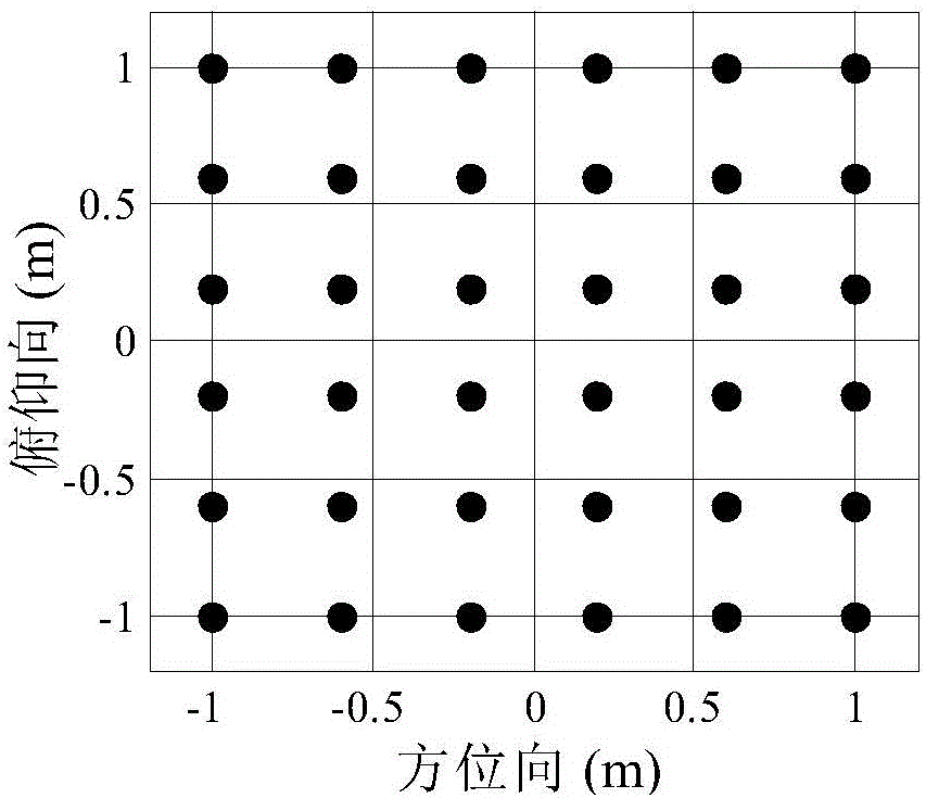
[0031] The present invention provides a two-dimensional sparse array configuration method for low-grating-lobe three-dimensional imaging radar. In this implementation, 36 antennas are included, the frequency of the transmitted signal is 0.5-3.0GHz, and the array size D=2m. The configuration method is specific Include the following steps:

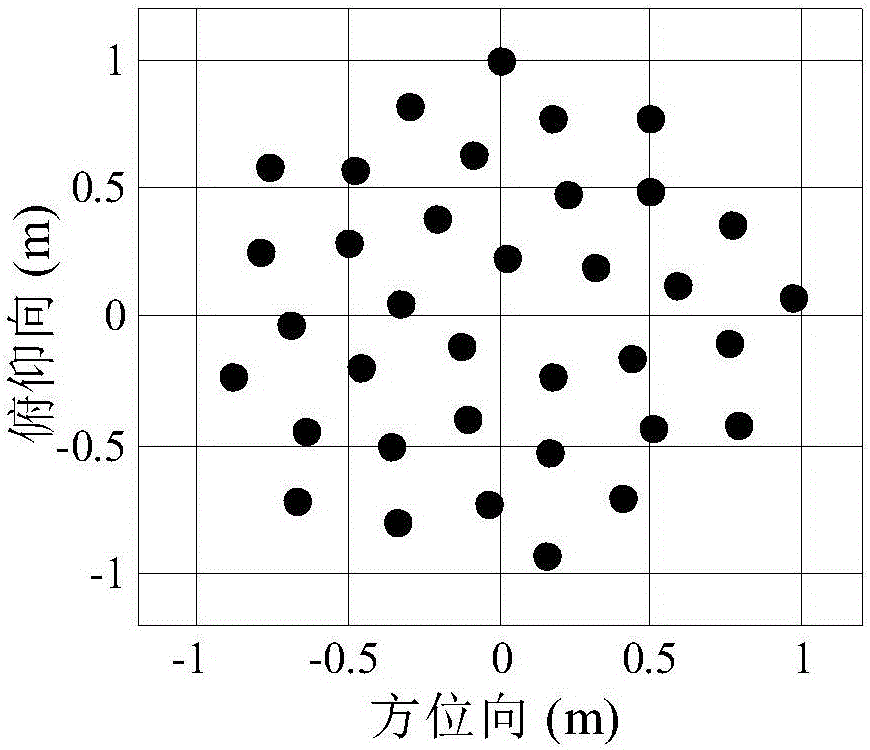
[0032] (1) First calculate the number of antennas N of each spiral arm according to the number of existing antennas EL and the number of arms N arm ;

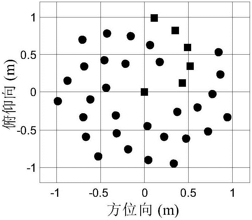
[0033] (2) Secondly, a spiral arm is designed according to the Fibonacci array, so that the first antenna is located in the center of the array as the common array element of all the spiral arms, and other antennas are designed according to the Fibonacci array;

[0034] (3) Finally, design a spiral arm based on the Fibonacci array to rotate ...


PUM


Abstract

The invention provides a low-grating lobe configuration method of a three-dimensional imaging radar two-dimensional sparse array. According to the method, a plurality of rotating arms are adopted, and strong grating lobes caused by a sparse array can be inhibited, and the inhibition performance of an imaging radar for false targets can be improved. The method includes the following steps that: the number of array elements contained by each rotating arm and the total number Narm of rotating arms are determined according to a given total number of array elements; one rotating arm is designed according to a Fibonacci array, the positions of array elements are represented by polar coordinates (r, theta), wherein the radius r is the linear function of the square root of the serial number of the array elements, and the angle theta of the array elements is increased linearly with the serial number of the array elements; and the rotating arm is rotated around the center of the array by 2pik/Narm(k=1,...,Narm-1), and a final array can be obtained. According to the method of the invention, the multi-rotating arm array of a rotary and symmetrical structure is designed, the number of array elements of which the projections are overlapped in any directions is small, and therefore, the problem of array element masking of a conventional two-dimensional array configuration method can be well solved, and a directional diagram with a low grating lobe level can be obtained, and detection for targets can be benefitted, and false targets can be inhibited.

Description

technical field [0001] The invention belongs to the field of three-dimensional imaging radar, and in particular relates to a method applicable to two-dimensional sparse array configuration. Background technique [0002] In order to ensure a certain azimuth resolution, the radar array must have a sufficiently large size; on the other hand, in order to save the cost of the 3D imaging radar and speed up signal processing, the radar uses a smaller number of antennas. In this way, the radar array is sparse, and the antenna spacing is greater than half a wavelength, and grating lobes will appear, resulting in false targets and seriously affecting radar performance. Therefore, the suppression of grating lobes has become an urgent problem for sparse array radars. [0003] The grating lobes are formed by the coherent superposition of the signals transmitted by each antenna. Therefore, the array configuration can be used to design appropriate array element positions and array element...

Claims


Application Information

Patent Timeline
Patent Type & Authority Applications(China)
IPC IPC(8): G01S13/89G01S7/28
CPCG01S7/2813G01S13/89
Inventor 朱国富涂新
Owner HUNAN TAIKANG ELECTRONICS INFORMATION TECH CO LTD
Why Eureka
Try Eureka