
A kind of mcu calibration method and system

A calibration method, a technology to be calibrated, applied in the detection of faulty computer hardware, etc., can solve the problems of affecting the operation effect of MCU, reducing the accuracy of results, and changing parameters

Active Publication Date: 2019-09-17
GIGADEVICE SEMICON (BEIJING) INC
View PDF8 Cites 0 Cited by
  • Summary
  • Abstract
  • Description
  • Claims
  • Application Information

AI Technical Summary

Problems solved by technology

[0006] The present invention provides a method and system for calibrating an MCU to solve the problem that the parameters corresponding to some modules in the MCU change due to changes in the application environment, thereby affecting the operation effect of the MCU and reducing the accuracy of the results

Method used


Image

  • A kind of mcu calibration method and system
  • A kind of mcu calibration method and system
  • A kind of mcu calibration method and system

Examples


Embodiment 1

[0051]In the embodiment of the present invention, the MCU is connected with the non-volatile memory. The MCU includes a calibration control unit and a module to be calibrated. Test calibration information is stored in the non-volatile memory. The test calibration information is the calibration information obtained during the test calibration of the MCU before leaving the factory.

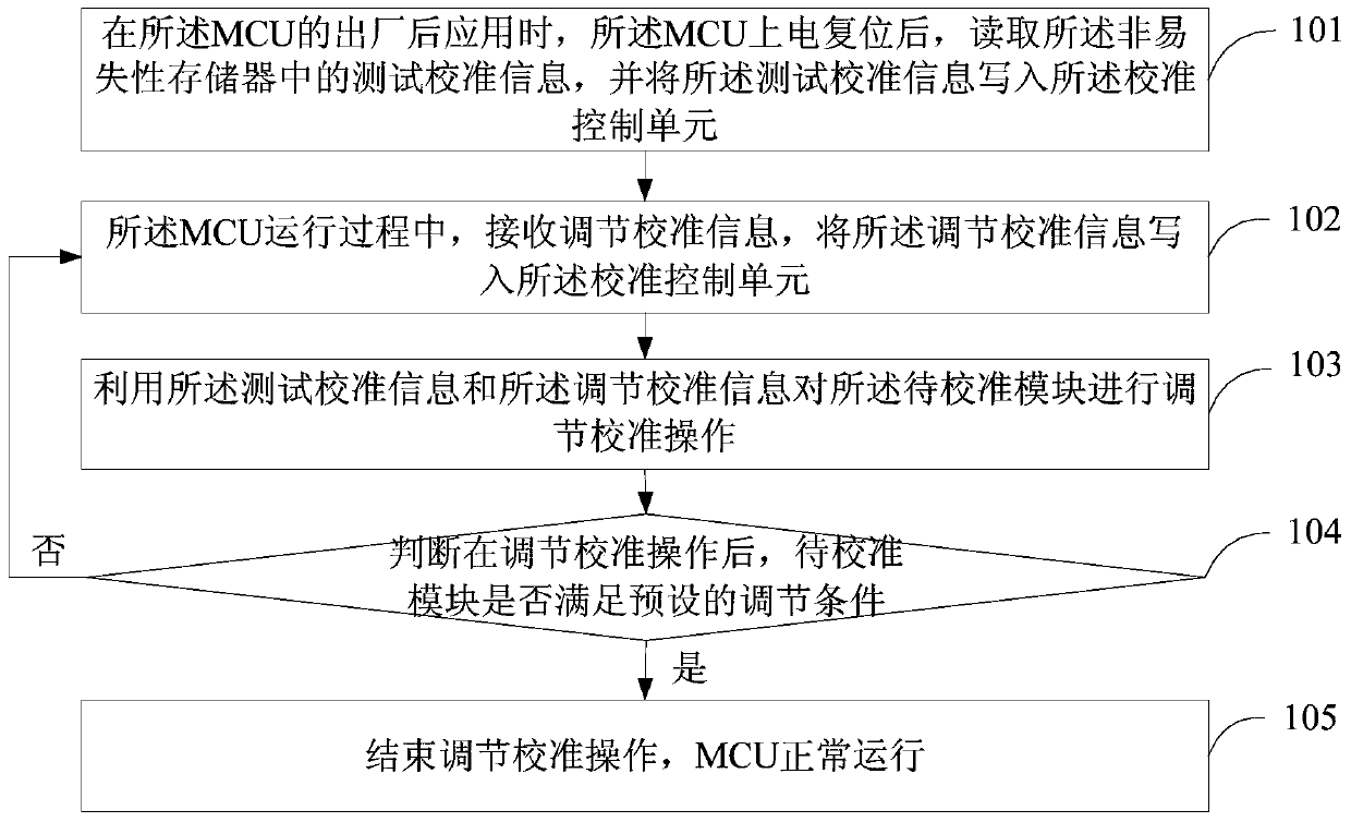
[0052] refer to figure 1 , shows a flow chart of the steps of an MCU calibration method according to Embodiment 1 of the present invention. The method may include the steps of:

[0053] Step 101, when the MCU is used after leaving the factory, after the MCU is powered on and reset, read the test calibration information in the non-volatile memory, and write the test calibration information into the calibration control unit .

[0054] Since the test and calibration operation has been performed on the MCU when the MCU is tested before leaving the factory, and the test and calibration information is ...

Embodiment 2

[0065] In the embodiment of the present invention, the non-volatile memory is described as an example of a flash memory chip, but the embodiment of the present invention is not limited to the non-volatile memory of the flash memory chip, any other non-volatile memory can be It works.

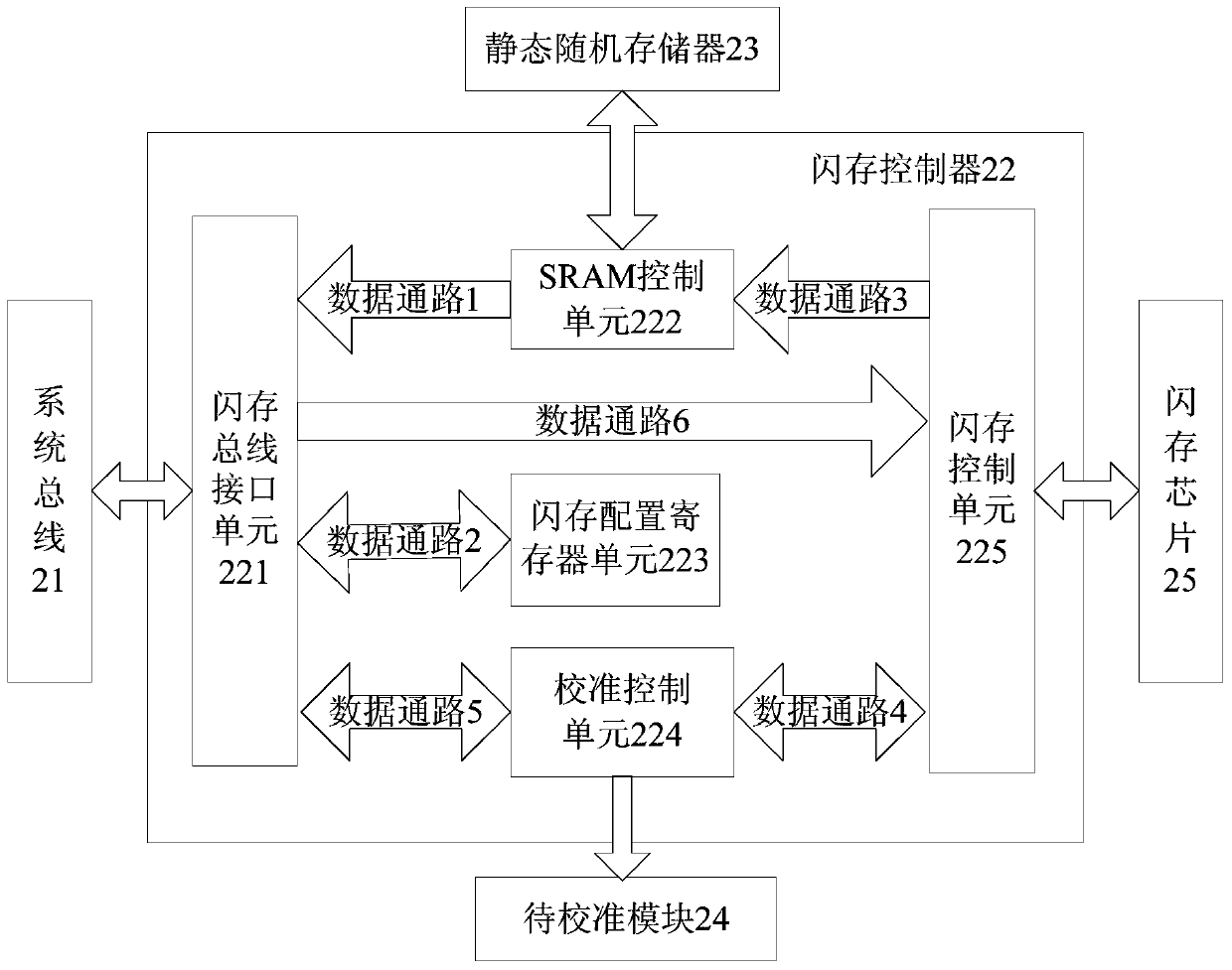
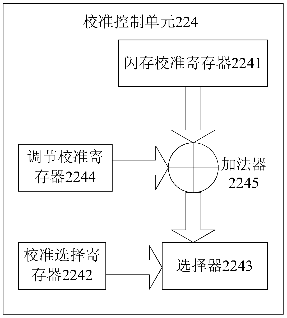
[0066] First, introduce the overall structure of the MCU in the embodiment of the present invention, as figure 2 As shown, the MCU may include: a system bus 21 , a flash memory controller 22 , a Static Random Access Memory (SRAM) 23 and a module 24 to be calibrated. The MCU is connected to the flash memory chip 25, and the MCU and the flash memory chip can be independent from each other and physically connected externally, or the flash memory chip can be integrated in the MCU.

[0067] In the embodiment of the present invention, the flash memory chip includes two parts: the program data part, which is used to store the program data of the MCU, and the program data is used for the programs and ...

Embodiment 3

[0155] refer to Figure 5 , shows a structural block diagram of an MCU calibration system according to Embodiment 3 of the present invention. The system may include: an MCU 51 and a non-volatile memory 52 connected to the MCU. In the embodiment of the present invention, the MCU and the non-volatile memory may be independent of each other and physically connected externally, or the non-volatile memory may permanent memory is integrated in the MCU. Test calibration information is stored in the non-volatile memory 52 , and the MCU 51 may include a calibration control unit 5101 and a module to be calibrated 5102 .

[0156] Wherein, the MCU 51 may also include:

[0157] The power-on reading module 5103 is used to read the test calibration information in the non-volatile memory after the MCU is powered on and reset when the MCU is applied after leaving the factory;

[0158] A power-on writing module 5104, configured to write the test calibration information into the calibration c...


PUM


Abstract

The invention discloses an MCU calibration method and system, and aims to solve the problem that the result accuracy is reduced because the running of an MCU is affected by changes in an application environment. The method comprises the following steps: after power-on reset of the MCU during post-delivery application, reading testing calibration information from a nonvolatile memory, and writing the testing calibration information into a calibration control unit; during the running of the MCU, receiving adjustment calibration information and writing the adjustment calibration information into the calibration control unit; carrying out adjustment calibration operations of a module to be calibrated through the testing calibration information and the adjustment calibration information; judging whether the module to be calibrated satisfies preset adjustment conditions after the adjustment calibration operations or not; and if the module to be calibrated fails to satisfy the preset adjustment conditions after the adjustment calibration operations, returning to the step in which the adjustment calibration information is received and written into the calibration control unit. The MCU calibration method and system provided by the invention have the advantages that parameters in the MCU that are changed due to the changes in the application environment can be calibrated, so that MCU running effects can be prevented from being affected, and the result accuracy can be improved.

Description

technical field [0001] The invention relates to the technical field of integrated circuits, in particular to an MCU calibration method and system. Background technique [0002] MCU (Micro Control Unit, Micro Control Unit), also known as SCM (Single Chip Microcomputer, single-chip microcomputer) or single-chip microcomputer, refers to the computer CPU (Central Processing Unit, Central processing unit), RAM (Random Access Memory, random access memory), ROM (Read-Only Memory, read-only memory), timer counter and various I / O interfaces are integrated on a chip to form a chip-level computer, providing different Do different combination control for different application occasions. [0003] In MCU production, it is generally necessary to perform some tests on the MCU (such as scan chain test, functional test, etc.), reject unqualified chips, and retain MCUs whose performance meets the requirements. And due to the uncertainty of the manufacturing process, there may be differences ...

Claims


Application Information

Patent Timeline
Patent Type & Authority Patents(China)
IPC IPC(8): G06F11/22
Inventor 王南飞李宝魁
Owner GIGADEVICE SEMICON (BEIJING) INC
Learn More