Portable scanner capable of forming area to be shot

A scanner and portable technology, applied in the field of scanners, can solve the problems of inconvenient portability, large base, and inability to use, and achieve the effect of improving efficiency, small size, and stable clamping

Inactive Publication Date: 2016-07-20
赵牧青
View PDF7 Cites 0 Cited by
  • Summary
  • Abstract
  • Description
  • Claims
  • Application Information

AI Technical Summary

Problems solved by technology

This kind of portable scanner has the following disadvantages: (1) Sometimes when there is no working table on site, this kind of portable scanner cannot stand, so it cannot be used
(2) In order to be able to stand stably, the base of this kind of portable scanner is generally made larger and heavier, which is inconvenient to carry and poor in portability
(3) When this kind of portable scanner is in use, due to the lack of positioning marks that traditional scanners possess to locate the piece to be scanned, in actual use, in order to obtain a better image, it is often necessary to adjust the piece to be scanned by hand multiple times. Getting it in place is time-consuming and laborious, and even then it is often difficult to obtain a satisfactory scanned image

Method used


Image

  • Portable scanner capable of forming area to be shot
  • Portable scanner capable of forming area to be shot
  • Portable scanner capable of forming area to be shot

Examples


Embodiment approach

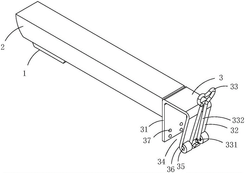
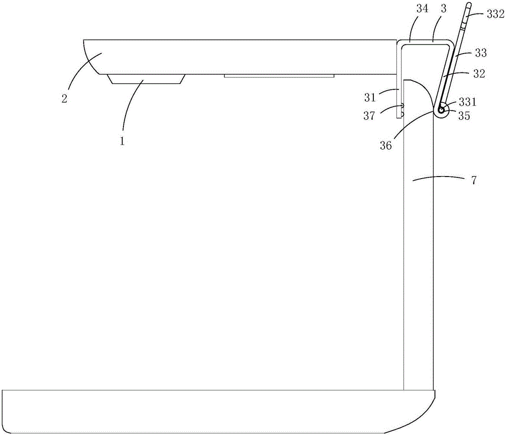
[0014] figure 1 and figure 2 A first embodiment of the invention is shown, in which figure 1 It is a schematic diagram of a three-dimensional structure of the first structure of the present invention; figure 2 Yes figure 1 A schematic diagram of a usage state of the portable scanner shown.

[0015] This embodiment is a portable scanner, see figure 1 and figure 2 As shown, it includes a base rod 2 provided with a photographic camera module 1 and a clamping mechanism 3 connected to the base rod; the clamping mechanism includes a fixed splint 31, an elastic splint 32 and a handle 33, the fixed splint and the elastic The splints are combined to form a clamping groove 34; the rear plate body of the elastic splint is bent to form a shaft hole 35; the handle includes a shaft connection part 331 and a grip part 332, and the shaft connection part 331 is arranged in the shaft hole.

[0016] In this embodiment, the fixed splint and the elastic splint are made integrally, and the...

Embodiment 2)

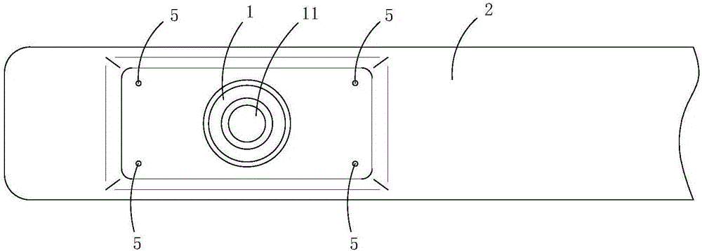
[0021] image 3 and Figure 4 A second embodiment of the invention is shown, in which image 3 It is a structural schematic diagram of the second structure of the present invention; Figure 4 Yes image 3 A schematic cross-sectional structure of the portable scanner shown.

[0022] This embodiment is basically the same as Embodiment 1, the difference is: see image 3 and Figure 4 As shown, the photo-taking camera module includes a lens 11 arranged on the base pole; the base pole is provided with an accommodation chamber 8, an illuminating lamp 4 positioned in the accommodation chamber, a group of light-transmitting holes 5 communicating with the accommodation chamber, and Induction switch 6 for controlling the illuminating lamp. The number of the group of light-transmitting holes is four, and the four light-transmitting holes are arranged symmetrically with the lens as the center. The area to be photographed; the cross-sectional shape of each light-transmitting hole is...

Embodiment 3)

[0027] Figure 5 and Image 6 A third embodiment of the invention is shown, in which Figure 5 It is a structural schematic diagram of the third structure of the present invention; Image 6 Time Figure 5 A schematic cross-sectional structure of the portable scanner shown.

[0028] This embodiment is basically the same as Embodiment 2, the difference is: see Figure 5 and Image 6 As shown, the base pole is provided with a plurality of lighting lamps and a plurality of groups of light-transmitting holes that cooperate with each lighting lamp and are used to enclose the transmitted light of each lighting lamp to form areas to be photographed of different sizes.

[0029] Specifically, the base rod in this embodiment is provided with three accommodating cavities 8, lighting lamps 4 located in each accommodating cavity, three groups of light-transmitting holes 5 communicating with each accommodating cavity, and three An infrared sensor switch 6 corresponding to an illuminati...


PUM


Abstract

The invention discloses a portable scanner capable of forming an area to be shot. The portable scanner comprises a base rod of a shooting type shooting module and a clamping connection mechanism connected with the base rod. The clamping connection mechanism comprises a fixed clamping plate, an elastic clamping plate and a handle, wherein the fixed clamping plate and the elastic clamping plate are combined to form a clamping groove, the tail plate body of the elastic clamping plate is bent to form a shaft hole, and the handle comprises a shaft connecting part and a holding part. The shaft connecting part is arranged in the shaft hole. The portable scanner is simple in structure, small in size, stable in clamp connection, and convenient to carry around. The portable scanner is more practical than a conventional portable scanner, and is applicable to various situations. The portable scanner is convenient to operate, and saves time. When the portable scanner is in use, the portable scanner is clamped and connected to the upper end of a display screen of a powered-on computer, a file to be scanned is placed on a keyboard of a computer host and no workbench is required for conveniently scanning. The portable scanner is especially suitable for outdoor use or use during riding on a train or an automobile.

Description

technical field [0001] The invention belongs to the technical field of scanners, and in particular relates to a portable scanner capable of forming an area to be photographed. Background technique [0002] Scanner is a kind of external computer equipment. By capturing images and converting them into digital devices that can be displayed, edited, stored and output by computers, traditional scanners used in work are generally large in size and inconvenient to carry. It can cause a lot of hassle when technical data needs to be scanned. [0003] In order to meet the needs of the market, there are existing portable scanners on the market. When in use, their bases are used to stand beside the computer and perform photographic scanning. This kind of portable scanner has the following disadvantages: (1) Sometimes when there is no working table on site, this kind of portable scanner can't stand, so it can't be used. (2) In order to be able to stand stably, the base of this kind of ...

Claims


Application Information

Patent Timeline
IPC IPC(8): H04N1/04H04N1/00
CPCH04N1/00246H04N1/00251H04N1/00519H04N1/00562H04N1/04
Inventor 不公告发明人
Owner 赵牧青
Why Eureka
Try Eureka