Portable scanner capable of forming area to be shot
A scanner, portable technology, applied in the field of scanners, can solve the problems of inconvenient carrying, unusable, large base, etc., and achieve the effect of small size, stable clamping and convenient operation
- Summary
- Abstract
- Description
- Claims
- Application Information
AI Technical Summary
Problems solved by technology
Method used
Image

Examples
Embodiment approach
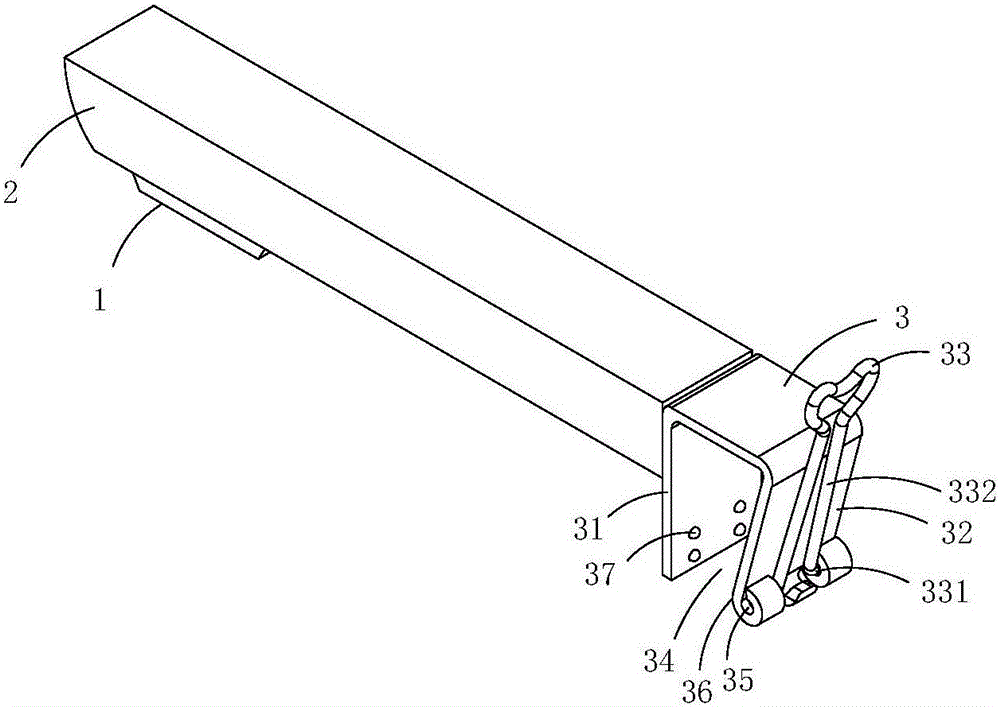
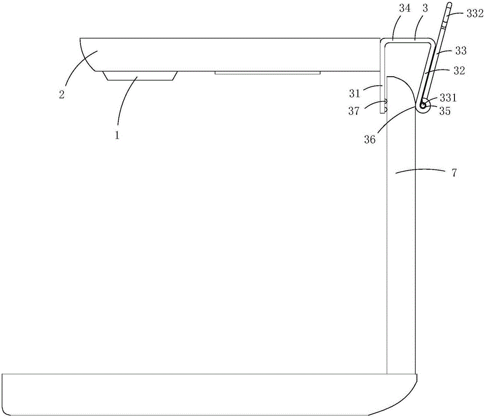
[0014] figure 1 and figure 2 A first embodiment of the invention is shown, in which figure 1 It is a schematic diagram of a three-dimensional structure of the first structure of the present invention; figure 2 yes figure 1 A schematic diagram of a usage state of the portable scanner shown.
[0015] This embodiment is a portable scanner, see figure 1 and figure 2 As shown, it includes a base rod 2 provided with a photographic camera module 1 and a clamping mechanism 3 connected to the base rod; the clamping mechanism includes a fixed splint 31, an elastic splint 32 and a handle 33, the fixed splint and the elastic The splints are combined to form a clamping groove 34; the rear plate body of the elastic splint is bent to form a shaft hole 35; the handle includes a shaft connection part 331 and a grip part 332, and the shaft connection part 331 is arranged in the shaft hole.
[0016] In this embodiment, the fixed splint and the elastic splint are made integrally, and the...
Embodiment 2)
[0021] image 3 and Figure 4 A second embodiment of the invention is shown, in which image 3 It is a structural schematic diagram of the second structure of the present invention; Figure 4 yes image 3 A schematic cross-sectional structure of the portable scanner shown.
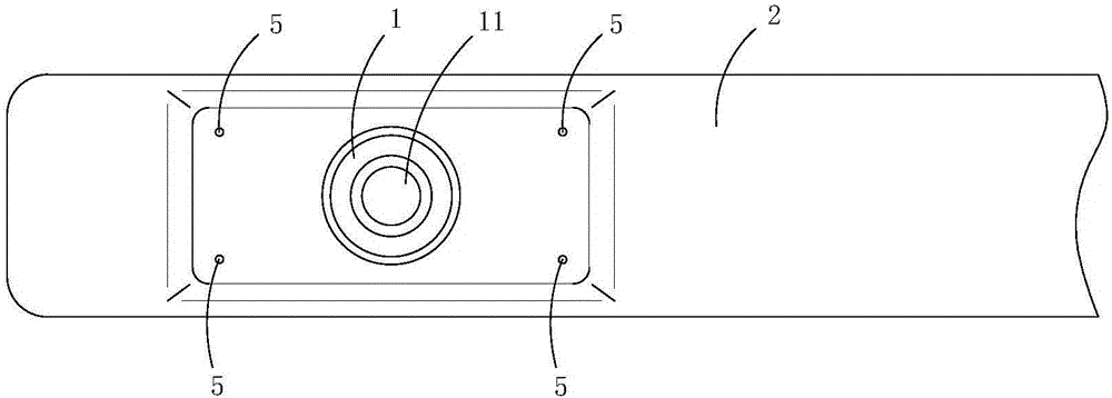
[0022] This embodiment is basically the same as Embodiment 1, the difference is: see image 3 and Figure 4 As shown, the photo-taking camera module includes a lens 11 arranged on the base pole; the base pole is provided with an accommodation chamber 8, an illuminating lamp 4 positioned in the accommodation chamber, a group of light-transmitting holes 5 communicating with the accommodation chamber, and Induction switch 6 for controlling the illuminating lamp. The number of the group of light-transmitting holes is four, and the four light-transmitting holes are arranged symmetrically with the lens as the center. The area to be photographed; the cross-sectional shape of each light-transmitting hole is...
Embodiment 3)
[0027] Figure 5 and Figure 6 A third embodiment of the invention is shown, in which Figure 5 It is a structural schematic diagram of the third structure of the present invention; Figure 6 Time Figure 5 A schematic cross-sectional structure of the portable scanner shown.
[0028] This embodiment is basically the same as Embodiment 2, the difference is: see Figure 5 and Figure 6 As shown, the base pole is provided with a plurality of lighting lamps and a plurality of groups of light-transmitting holes that cooperate with each lighting lamp and are used to enclose the transmitted light of each lighting lamp to form areas to be photographed of different sizes.
[0029] Specifically, the base rod in this embodiment is provided with three accommodating cavities 8, lighting lamps 4 located in each accommodating cavity, three groups of light-transmitting holes 5 communicating with each accommodating cavity, and three An infrared sensor switch 6 corresponding to an illumin...
PUM
 Abstract
Description
Claims
Application Information
 - R&D Engineer
- R&D Manager
- IP Professional
- Industry Leading Data Capabilities
- Powerful AI technology
- Patent DNA Extraction
Browse by: Latest US Patents, China's latest patents, Technical Efficacy Thesaurus, Application Domain, Technology Topic.
© 2024 PatSnap. All rights reserved.Legal|Privacy policy|Modern Slavery Act Transparency Statement|Sitemap