Powder feeding device and using method thereof
A powder feeding device and powder feeding nozzle technology, which is applied in the coating process of metal materials, coating, etc., can solve the problem that the distance between the powder outlet and the surface of the substrate cannot be fine-tuned accurately, the effective utilization rate of cladding powder is low, and the cladding process Adverse effects and other issues, to achieve the effect of improving effective utilization, increasing service life, and strong practicability
- Summary
- Abstract
- Description
- Claims
- Application Information
AI Technical Summary
Problems solved by technology
Method used
Image
Examples
Embodiment 1
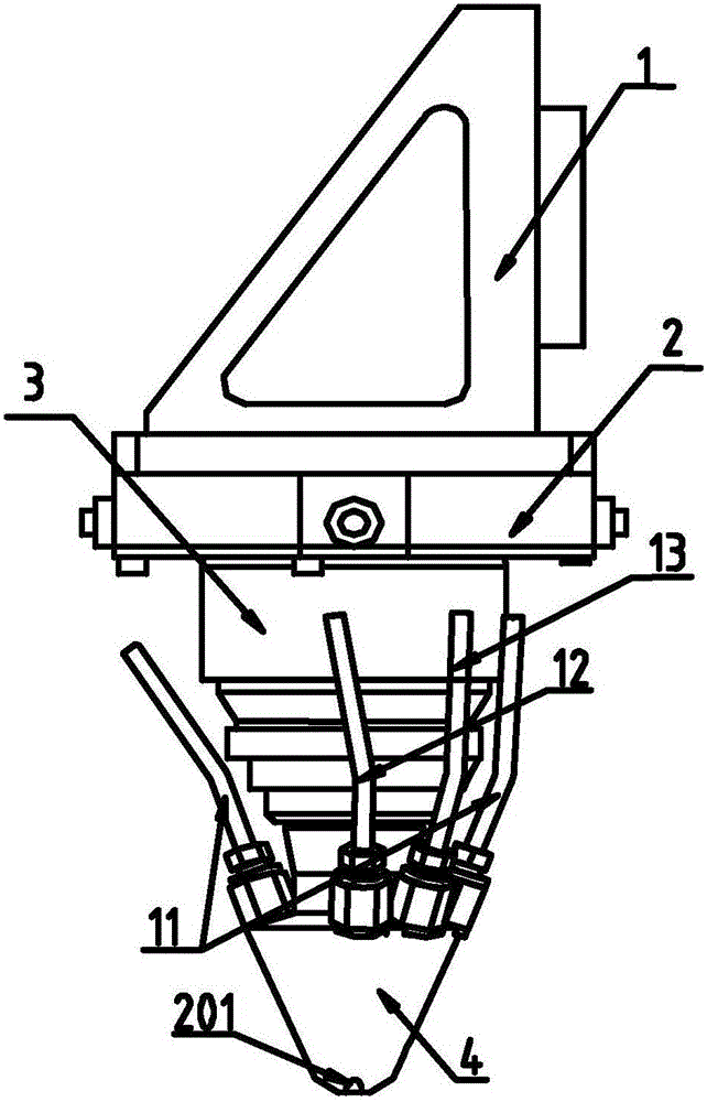
[0041] Such as figure 1 As shown, a powder feeding device includes a fixed part 1 and a powder feeding nozzle 4, an adjustment device is provided between the fixed part 1 and the powder feeding nozzle 4, and the adjustment device includes a horizontal adjustment part 2 and a vertical adjustment part 3 , the vertical adjustment part 3 is located inside the horizontal adjustment part 2, through the synergistic effect of the horizontal adjustment part 2 and the vertical adjustment part 3, the distance between the powder outlet 201 and the surface of the substrate is adjusted, which has high flexibility and contributes to To improve the quality of cladding, the powder feeding device is connected with the laser.
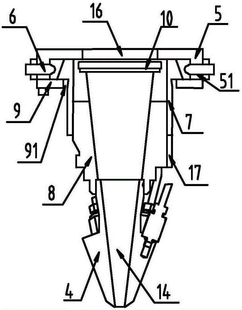
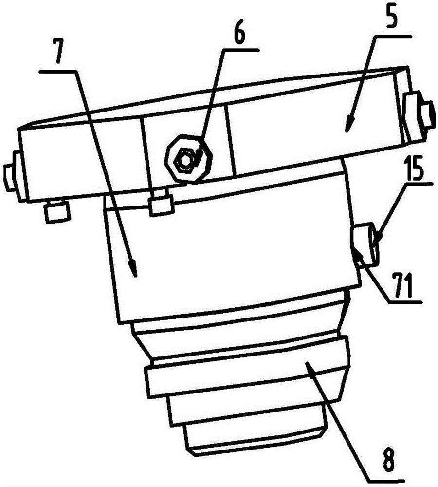
[0042] Such as Figure 1-2 As shown, the horizontal adjustment part 2 includes an adjustment plate 5 and an adjustment piece 6, the adjustment plate 5 is set as a concave structure, the middle part is provided with a through hole 16, and its frame is provided with an adj...
Embodiment 2
[0048] Such as figure 1 , figure 2 , Figure 5 with Image 6 As shown, the powder feeding nozzle 4 is arranged in a conical structure, and a laser channel 14 is arranged inside the conical structure, and at least two powder feeding channels 20 are uniformly arranged on the conical wall of the conical structure. A powder outlet 201 is provided at the bottom of the powder feeding channel 20, the powder feeding channel 20 is connected to the powder feeding pipe 11, and the included angle between the central axis of the powder feeding channel 20 and the central axis of the laser channel 14 is 15-25° , as a preference, the included angle is 15°, 20°, 25°, which can not only ensure a certain distance between the powder feeding channel 20 and the laser channel 14, reduce the probability of the powder feeding tube 11 being burned out, but also ensure that The laser focus and cladding powder converge at one point, which improves the effective utilization rate and cladding quality o...
Embodiment 3
[0051] Such as Figure 1-7 As shown, the specific use of the powder feeding device includes the following steps:
[0052] (1) Synchronously adjust the adjustment member-6 on the opposite frame of the adjustment plate 5, wherein one adjustment member-6 performs a loosening operation, and the other one opposite to it performs a tightening operation, driving the adjustment cylinder 7 in the hollow structure 91 internal movement in all directions;
[0053] (2) After the center of the protective lens 10 coincides with the center of the through hole 16, stop adjusting the adjusting part 16 to ensure that the laser focus and the cladding powder converge at one point, and improve the effective utilization rate and cladding powder of the cladding powder. quality;
[0054] (3) Loosen the adjusting part 2 15, impel the adjusting part 2 15 to slide up and down along the slideway 81, and change the distance between the powder outlet 201 and the surface of the substrate;
[0055] (4) Whe...
PUM
 Abstract
Description
Claims
Application Information
 - R&D
- Intellectual Property
- Life Sciences
- Materials
- Tech Scout
- Unparalleled Data Quality
- Higher Quality Content
- 60% Fewer Hallucinations
Browse by: Latest US Patents, China's latest patents, Technical Efficacy Thesaurus, Application Domain, Technology Topic, Popular Technical Reports.
© 2025 PatSnap. All rights reserved.Legal|Privacy policy|Modern Slavery Act Transparency Statement|Sitemap|About US| Contact US: help@patsnap.com


