Multifunctional overflow valve for teaching and practical training and operation method

A multi-functional, relief valve technology, applied in the field of hydraulic valves, to achieve the effect of high use value, compact structure and ingenious design

Active Publication Date: 2016-07-27
SHANDONG DOLANG TECH EQUIP
View PDF6 Cites 2 Cited by
  • Summary
  • Abstract
  • Description
  • Claims
  • Application Information

AI Technical Summary

Problems solved by technology

However, the rapid development of modern hydraulic transmission towards diversification, especially the development of construction machinery hydraulic pressure puts forward more requirements for hydraul

Method used


Image

  • Multifunctional overflow valve for teaching and practical training and operation method
  • Multifunctional overflow valve for teaching and practical training and operation method
  • Multifunctional overflow valve for teaching and practical training and operation method

Examples


Example Embodiment

[0021] Example 1

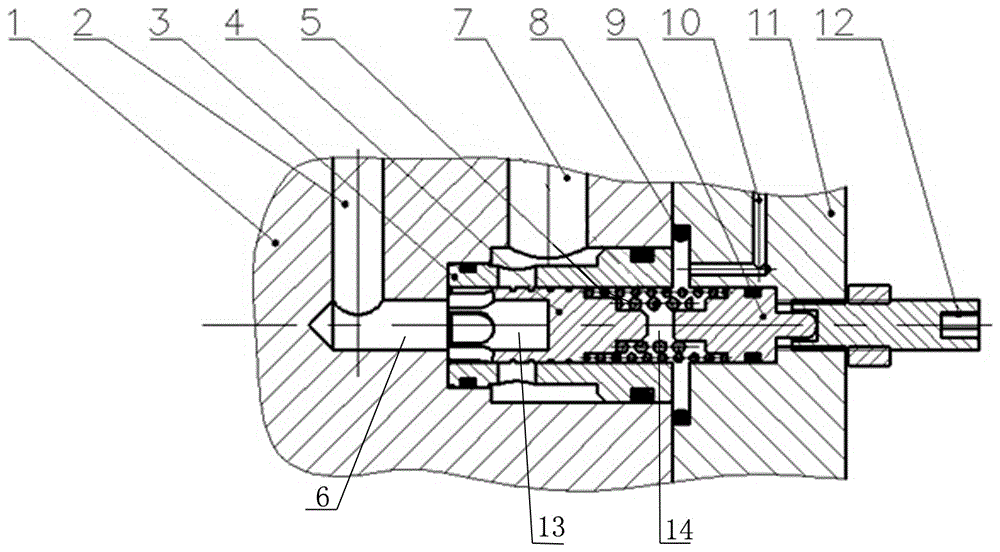
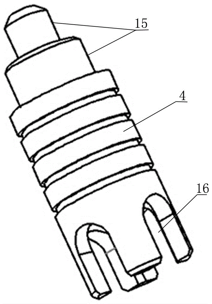
[0022] Such as figure 1 As shown, a multifunctional relief valve for teaching and training includes a valve body with a valve cavity 1, a valve sleeve 3 installed in the valve cavity, and a valve core 4 slidably arranged in the valve sleeve 3. The valve sleeve 3 The valve cavity is divided into left cavity 6, middle cavity 13, right cavity 14 with spool 4. The valve body 1 is provided with high pressure oil inlet 2, zero pressure oil return port 7 and control oil port 10, high pressure oil inlet 2 , The zero-pressure oil return port 7 and the control oil port 10 are connected to the left cavity 6, the middle cavity 13, and the right cavity 14 respectively through the oil channel; one end of the valve core 4 is provided with a spring guide seat 9, the valve core 4 and the spring guide seat There are two springs 5 ​​with different rigidity between 9 and the two ends of the spring 5 are respectively pressed on the valve core 4 and the spring guide seat 9; the oth...

Example Embodiment

[0026] Example 2

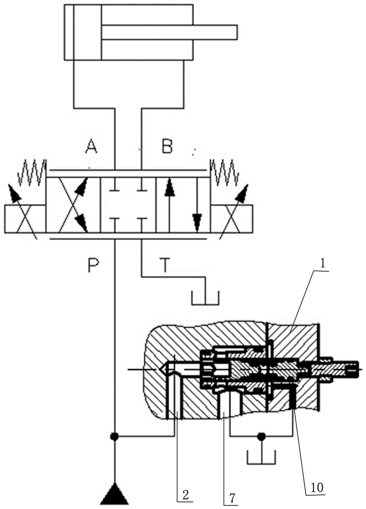
[0027] This embodiment discloses an operating method of a multifunctional relief valve for teaching and training. At this time, the relief valve is used as a traditional relief valve, such as image 3 As shown, the high-pressure oil inlet 2 is connected to the pressure oil outlet, and the zero-pressure oil return port 7 and the control oil port 10 are connected to the oil tank. The pressure oil enters the valve body 1 from the high-pressure oil inlet 2 and acts on the valve core 4. When the spring force is greater than the set value of the spring force, the valve core 4 slides to the right, the pressure oil is discharged from the zero-pressure oil return port 7 into the oil return tank, and the system pressure is changed by adjusting the adjusting screw 12. At this time, the multifunctional relief valve for teaching and training is used as a traditional relief valve, but a larger system pressure can be obtained by adjusting the adjustment screw 12, which can be ...

Example Embodiment

[0029] Example 3

[0030] This embodiment discloses another operation method of a multifunctional relief valve for teaching and training. At this time, the relief valve is used as a fixed differential relief valve, such as Figure 4 As shown, the high-pressure oil inlet 2 is connected to the pressure oil outlet, the zero-pressure oil return port 7 is connected to the mailbox, and the control oil port 10 is connected to the system's highest load pressure detection port. The pressure oil enters the valve body from the high-pressure oil inlet 2 and acts on the valve. At the left end of the core 4, the highest load pressure of the system and the spring force act together on the right part of the core 4, and a force balance is established in the core 4 after stabilization, namely F left =F right +F bomb , F left Supply the force generated by the pressure at the left end of the spool 4 to the system, F right Is the force generated by the highest load pressure of the system at the rig...


PUM


Abstract

The invention discloses a multifunctional overflow valve for teaching and practical training. The multifunctional overflow valve is designed and developed for meeting the teaching and practical training requirement of vocational education and can meet the requirements of principle verification type practical training and actual simulation type practical training for students. The multifunctional overflow valve comprises a valve body, a valve sleeve installed inside the valve body, a valve core with an oval groove, springs different in rigidity and a control cover plate. Through the valve core with the oval groove, the pressure impact at the opening moment of the overflow valve can be effectively lowered, and the influence of the medium temperature on the performance of the overflow valve can be lowered; through the springs different in rigidity, the requirements of principle verification type practical training and actual simulation type practical training both can be met; through different connection modes of a control oil port, the control principle of the multifunctional overflow valve is changed, and the functions of fixed-value overflow and fixed-difference overflow are realized. The multifunctional overflow valve for teaching and practical training is ingenious in design, compact in structure, capable of realizing multiple functions and capable of being applied to various conditions of teaching and practical training, effectively opens minds of the students, and enhances understanding of the students about hydraulic pressure knowledge.

Description

technical field [0001] The invention relates to a hydraulic valve, in particular to a multifunctional overflow valve for teaching and training, which belongs to the technical field of hydraulic valves. Background technique [0002] Hydraulic training teaching equipment is designed and developed to meet the teaching and training requirements of mechanical engineering and mechatronics majors in colleges, technical schools, and vocational schools. Through operation experiments and course design, students can accurately grasp the structure of hydraulic components, control principles and design methods of hydraulic systems. However, the rapid development of modern hydraulic transmission towards diversification, especially the development of construction machinery hydraulic pressure puts forward more requirements for hydraulic valves used in teaching and training, and the single-function and single-principle hydraulic valve components in teaching equipment are increasingly unable ...

Claims


Application Information

Patent Timeline
IPC IPC(8): F15B13/02
CPCF15B13/02
Inventor 杜德昌刘寒姚建岭魏利赵京伟张振东赵贵森
Owner SHANDONG DOLANG TECH EQUIP
Why Eureka
Try Eureka