
Gyro-free inertial system error calibration method

An inertial system and error calibration technology, applied in the field of inertial navigation, can solve the problems of no gyro inertial system error, accelerometer installation error cannot be estimated and other problems

Active Publication Date: 2016-07-27
NAT UNIV OF DEFENSE TECH
View PDF6 Cites 20 Cited by
  • Summary
  • Abstract
  • Description
  • Claims
  • Application Information

AI Technical Summary

Problems solved by technology

[0006] The purpose of the present invention is to provide a method for calibrating errors of gyro-free inertial systems, which solves the technical problem that multiple installation errors of accelerometers in gyro-free inertial systems cannot be estimated

Method used


Image

  • Gyro-free inertial system error calibration method
  • Gyro-free inertial system error calibration method
  • Gyro-free inertial system error calibration method

Examples


Embodiment Construction

[0068] The drawings constituting a part of the present application are used to provide a further understanding of the present invention, and the exemplary embodiments and descriptions of the present invention are used to explain the present invention, and do not constitute an improper limitation of the present invention.

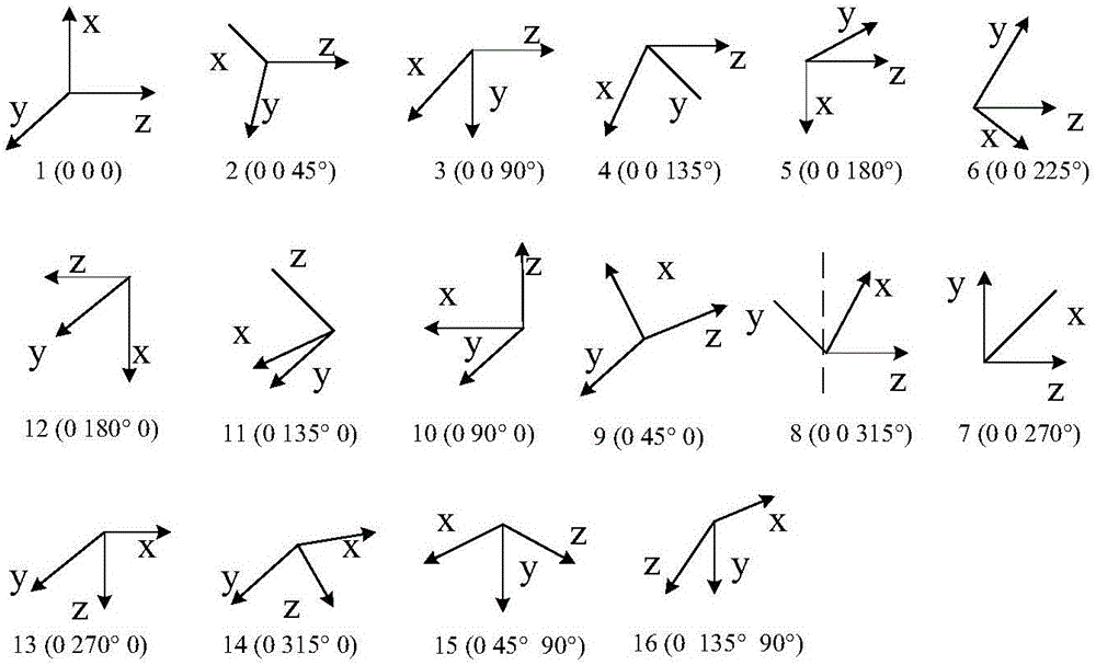
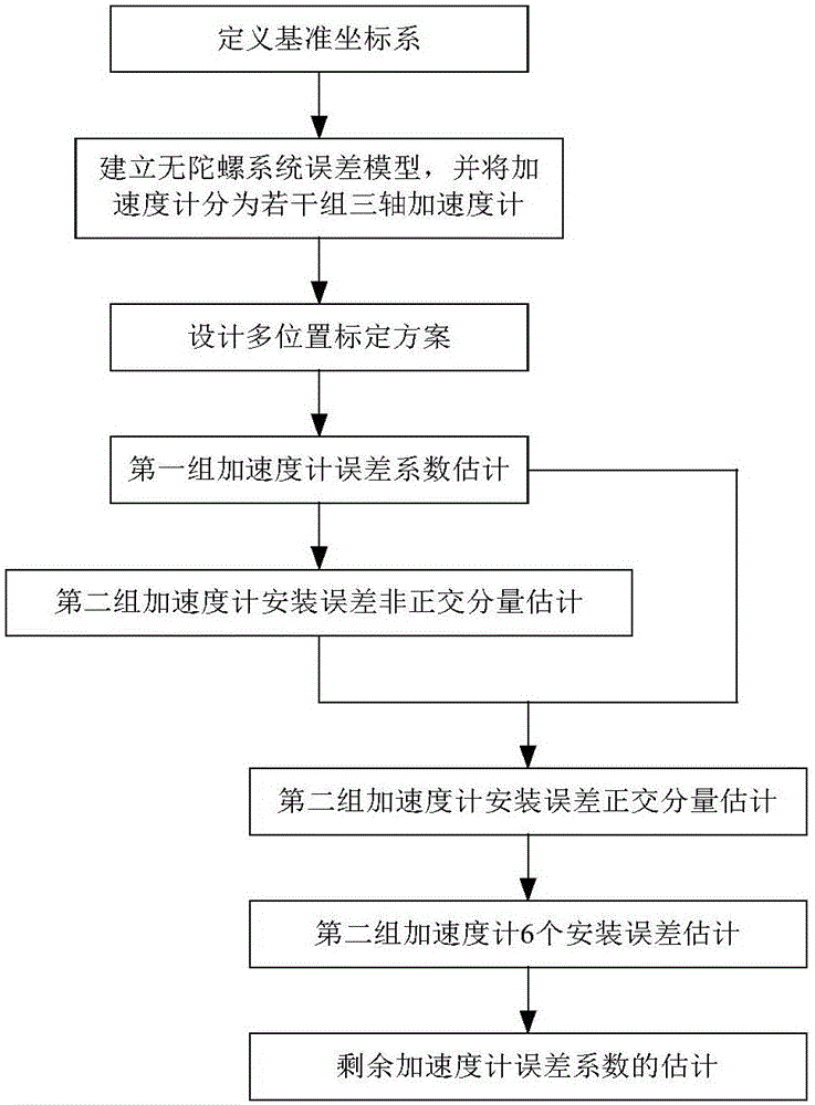
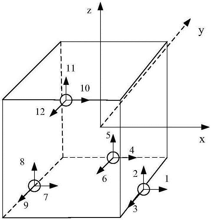
[0069] The method provided by the present invention takes advantage of the constant value of the gravity vector modulus at any point on the earth, by changing the attitude of the three-axis of the gyro-free inertial system relative to the ground, all acceleration output combinations at multiple attitude positions are obtained, and the nonlinear iterative method is used to estimate The zero offset coefficient, scale factor error, and installation error of all accelerometers are calculated. For the convenience of description, the method provided by the present invention is only applicable to the case where the non-gyro inertial system includes N=3n (n is a positiv...


PUM


Abstract

The invention provides a gyro-free inertial system error calibration method.According to the method, accelerometer output combinations at multiple positions are formed by changing space positions of a gyro-free inertial system reference coordinate system by means of the uniqueness of a gravity vector module value under the condition that no external equipment provides a reference, and zero offset, scale factor errors and installation errors of all accelerometers of a gyro-free inertial system are estimated by adopting a nonlinear iterative method.The method has the advantages that no precise external equipment is needed, operation is simple and the cost is low, and can be used for calibration of the gyro-free inertial system in a laboratory or external environment.

Description

Technical field [0001] The invention relates to the technical field of inertial navigation, in particular to a method for calibrating errors of a gyroless inertial system. Background technique [0002] Gyroless strapdown inertial navigation system is an inertial system that only uses an accelerometer as a measurement sensitive element, and the angular velocity and linear acceleration of the carrier are obtained from the accelerometer output. Although its theoretical basis was proposed as early as the 1960s, system development has not been carried out due to various constraints. With the breakthroughs in microelectronics and micromechanical manufacturing technologies in recent years, it has become possible to manufacture low-cost, high-precision micro-accelerometers. Moreover, from a technical point of view, manufacturing micro-accelerometers is easier and cheaper than manufacturing micro-gyros. [0003] Many local wars after the Gulf War have shown that modern wars are very expens...

Claims


Application Information

Patent Timeline
IPC IPC(8): G01C25/00
CPCG01C25/00
Inventor 杨华波丁智坚张士峰
Owner NAT UNIV OF DEFENSE TECH
Learn More