
Backlight module and display device

A backlight module and light source technology, applied in optics, nonlinear optics, instruments, etc., can solve the problems affecting the display effect of display devices, bright edges, light leakage, etc., and achieve the effect of improving the display effect and reducing the warping of the diffuser

Inactive Publication Date: 2016-07-27
BOE TECH GRP CO LTD +1
View PDF12 Cites 9 Cited by
  • Summary
  • Abstract
  • Description
  • Claims
  • Application Information

AI Technical Summary

Problems solved by technology

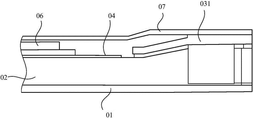
[0005] like figure 2 as shown, figure 2 It is a schematic diagram of the structure of the backlight module in the prior art. A prism layer 06 is arranged above the diffusion sheet 04. Since there is a gap between the prism layer 06 and the flexible circuit board 05, the light emitted by the light source is easy to radiate to the display panel from the gap. Cause serious light leakage in front of the lamp and bright edge phenomenon, which affects the display effect of the display device

Method used


Image

  • Backlight module and display device
  • Backlight module and display device
  • Backlight module and display device

Examples


Embodiment Construction

[0036] The following will clearly and completely describe the technical solutions in the embodiments of the present invention with reference to the accompanying drawings in the embodiments of the present invention. Obviously, the described embodiments are only some, not all, embodiments of the present invention.

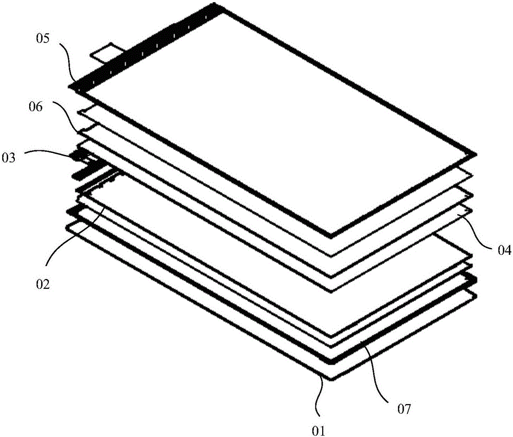
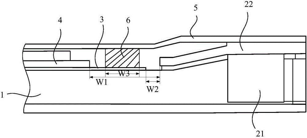
[0037] Such as image 3 and Figure 4 shown, where: image 3 A schematic structural diagram of a backlight module provided by an embodiment of the present invention; Figure 4 Another schematic diagram of the structure of the backlight module provided by the embodiment of the present invention. The present invention provides a backlight module, comprising: a light guide plate 1, a light source 2 located on the light incident side of the light guide plate 1, a diffusion sheet 3 located on the light output side of the light guide plate 1, and a diffusion sheet 3 located on the side away from the light guide plate 1 The prism layer 4 and the light-shielding tape 5 on...


PUM


Abstract

The invention relates to the technical field of displays and discloses a backlight module and a display device, aiming at reducing situations that a diffuser is warped up, edges of a light outlet surface of a backlight source are brightened and the brightness and darkness are not even, and improving the display effect of the display device. The backlight module comprises a light guide plate, a light source on an incident side of the light guide plate, the diffuser on an emergent side of the light guide plate, a lens layer on one side, opposite to the light plate, of the diffuser, and a shading tape on the periphery of the light outlet surface of the backlight module, and further comprises a flexible light absorbing material layer on one side, towards the light guide plate, of the shading tape, wherein the flexible light absorbing material layer is attached to the part, close to the emergent side of the light guide plate, of the shading tape, and the side, opposite to the shading tape, of the flexible light absorbing material layer resists against the side, opposite to the light guide plate, of the diffuser.

Description

technical field [0001] The invention relates to the technical field of display preparation, in particular to a backlight module and a display device. Background technique [0002] Liquid crystal display (Liquid Crystal Display, LCD) has many advantages such as thin body, power saving, and no radiation, and has been widely used, such as mobile phones, personal digital assistants (PDAs), digital cameras, computer screens or notebook computer screens. [0003] Most of the liquid crystal display devices currently on the market are backlight liquid crystal display devices, which include a housing, a liquid crystal panel disposed in the housing, and a backlight module disposed in the housing. Since the liquid crystal panel itself does not emit light, the light source provided by the backlight module is needed to display images normally. Therefore, the backlight module becomes one of the key components of the liquid crystal display device. Backlight modules are divided into side-t...

Claims


Application Information

Patent Timeline
IPC IPC(8): G02F1/13357
CPCG02F1/1336G02F1/133603G02F1/133605G02F1/133607
Inventor 裴效增
Owner BOE TECH GRP CO LTD
Learn More