Liquid crystal display screen

A liquid crystal display and glass substrate technology, applied in the direction of instruments, nonlinear optics, optics, etc., can solve the problems of large loss of optical efficiency of the backlight module, poor display effect of the display panel, etc., and achieve the effect of reducing the overall thickness

Pending Publication Date: 2016-07-27
KUSN INFOVISION OPTOELECTRONICS
12 Cites 10 Cited by

AI-Extracted Technical Summary

Problems solved by technology

In the prior art, reducing the thickness of the liquid crystal display usually adopts reducing the thickness of the glass substrate and reducing the thickness of the light guide plate and the optical film group in the backlight module. However, when the thickness of the glass substrate is too thin and is reduced to less than 2mm , the display effect of the liq...

Method used

In the present embodiment, reflective layer 61 is formed on the lower surface of lower glass substrate 6, and reflective sheet 7 is in contact with reflective layer 61, and reflective layer 61 is set between reflective sheet 7 and lower glass substrate 6 and can improve reflection The reflectivity of the sheet 7 is increased to improve the utilization rate of the backlight source 8 .
Liquid crystal display screen of the present invention, by affixing backlight source 8 on one side of lower glass substrate 6, reflective layer 61 is formed on the lower surface of lower glass substrate 6, destroys the total reflection of light in lower glass substrate 6, thereby makes The light reaches the upper surface of the lower glass substrate 6 to form outgoing light, passes through the composite optical layer 5 to form a uniform light-emitting surface, and is converted into polarized light through the metal wire grid polarizing plate 4, omitting the light guide plate of the liquid crystal display in the prior art, thereby The overall thickness of the liquid crystal display screen of the present invention is greatly reduced.
Please refer to Fig. 1 and Fig. 3 simultaneously, Fig. 3 is the structural representation of the lower glass substrate in Fig. 1, in the present embodiment, the formation process of reflective layer 61 comprises the following steps: by etching process on the lower glass substrate 6 The bottom surface makes the bottom ...

Abstract

The invention discloses a liquid crystal display screen. The liquid crystal display screen comprises an upper polaroid, an upper glass substrate, a liquid crystal layer, a metal wire grating polarizer, a composite optical layer and a lower glass substrate which are arranged in sequence from top to bottom, and further comprises a reflective sheet and a backlight source, wherein the backlight source is arranged on one side of the lower glass substrate; the reflective sheet coats the lower glass substrate and the backlight source; the top surface of the lower glass substrate is exposed out of the reflective sheet; the metal wire grating polarizer comprises a polarization substrate and a plurality of electrode strips which are formed on the polarization substrate through an etching process; the composite optical layer is used for adjusting light rays emitted from the upper surface of the lower glass substrate in order to form surface sources which are uniformly distributed. By adopting the liquid crystal display screen, a light guide plate of the liquid crystal display screen in the prior art is omitted, so that the overall thickness of the liquid crystal display screen is reduced greatly.

Application Domain

Technology Topic

Image

  • Liquid crystal display screen
  • Liquid crystal display screen
  • Liquid crystal display screen

Examples

  • Experimental program(1)

Example Embodiment

[0020] In order to make the objectives, technical solutions, and advantages of the present invention clearer, the following further describes the embodiments of the present invention with reference to the accompanying drawings.
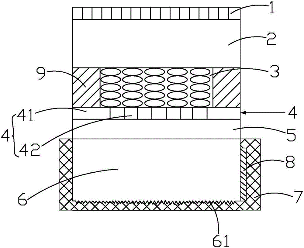
[0021] Please refer to figure 1 , figure 1 It is a schematic structural diagram of a liquid crystal display screen implemented in the present invention. The embodiment of the present invention provides a liquid crystal display screen, which includes an upper polarizer 1, an upper glass substrate 2, a liquid crystal layer 3, a metal wire grid polarizer 4, a composite optical layer 5, and a lower polarizer. Glass substrate 6, reflection sheet 7, and backlight 8.
[0022] The upper polarizer 1, the upper glass substrate 2, the liquid crystal layer 3, the metal wire grid polarizer 4, the composite optical layer 5, and the lower glass substrate 6 are arranged in sequence from top to bottom. Among them, the metal wire grid polarizing plate 4 includes a polarizing base 41 and a plurality of electrode strips 42 formed on the polarizing base 41 through an etching process. The function of the polarizing base 41 in the metal wire grid polarizing plate 4 is similar to that of a conventional liquid crystal display. The functions of the lower polarizer and the electrode strips are the same, and will not be repeated here. The composite optical layer 5 is used to adjust the light emitted from the upper surface of the lower glass substrate 6 to form a uniformly distributed surface light source.
[0023] The backlight source 8 is arranged on one side of the lower glass substrate 6. The reflective sheet 7 covers the lower glass substrate 6 and the backlight source 8, and the top surface of the lower glass substrate 6 is exposed from the reflective sheet 7.
[0024] Specifically, in this embodiment, the reflective sheet 7 is box-shaped, the top of the reflective sheet 7 is open, the lower glass substrate 6 and the backlight source 8 are located in the reflective sheet 7, and the top surface of the lower glass substrate 6 faces the reflective sheet The opening of 7, that is, the reflection polarization 7 will wrap the lower glass substrate 6 and the backlight source 8, so that the light emitted by the backlight source 8 is basically not diverged to the outside, so that the light emitted by the backlight source 8 can be utilized to the greatest extent, improving Utilization efficiency of backlight source 8. It should be noted that the reflective sheet 7 may be integrally formed, or a box-shaped structure surrounded by a plurality of sheet-shaped sub-reflective sheets.
[0025] In this embodiment, the top surface of the lower glass substrate 6 is flush with the opening of the reflective sheet 7, and the top surface of the backlight source 8 abuts against the bottom surface of the top of the reflective sheet 7 to fully reflect light and prevent light leakage.
[0026] In this embodiment, a reflective layer 61 is formed on the lower surface of the lower glass substrate 6, and the reflective sheet 7 is in contact with the reflective layer 61. Providing the reflective layer 61 between the reflective sheet 7 and the lower glass substrate 6 can improve the performance of the reflective sheet 7 Reflectivity to improve the utilization of the backlight source 8.
[0027] figure 2 Yes figure 1 Schematic diagram of the composite optical layer in the figure 2 As shown, the composite optical layer 5 includes a prism layer 51 and an upper diffusion layer 52 disposed on the top surface of the prism layer 51. Wherein, the upper diffusion layer 52 is used to make the light emitted from the upper surface of the lower glass substrate 6 form a uniformly distributed surface light source, and the prism layer 51 is used to gather the light emitted from the upper surface of the lower glass substrate 6 to improve the brightness of the central viewing angle.
[0028] The prism layer 51 includes a prism base 511 and a prism layer filler 512 formed on the top surface of the prism base 511. The upper diffusion layer 52 includes a diffusion base 521 and a diffusion layer filler 522 formed on the top surface of the diffusion base 521. Wherein, the refractive index of the material forming the prism base 511 and the diffusion base 521 is a high refractive index material, for example, an inorganic material such as Si 3 Nx 4 Or LaTiO 3 , The refractive index is about 2.0, or the high refractive index resin material, such as sulfur-containing resin material can reach 1.7, the refractive index of the material forming the prism layer filler 512 and the diffusion layer filler 522 is a low refractive index material, such as ordinary resin Material, the refractive index is around 1.4
[0029] In this embodiment, the composite optical layer 5 further includes a lower diffusion layer 53 disposed on the bottom surface of the prism layer 51, and the structure of the lower diffusion layer 53 is the same as that of the upper diffusion layer 52, which will not be repeated here.
[0030] In this embodiment, the liquid crystal display screen of the present invention further includes a sealing layer 9 provided between the upper glass substrate 2 and the metal wire grid polarizing plate 4 for sealing the liquid crystal layer 3.
[0031] Please also refer to figure 1 with image 3 , image 3 Yes figure 1 In the present embodiment, the formation process of the reflective layer 61 includes the following steps: the bottom surface of the lower glass substrate 6 is zigzag on the bottom surface of the lower glass substrate 6 through an etching process; Organic materials are coated on the bottom surface to form grooves or dots, so that the reflective layer 61 has the function of enhancing reflection when it is matched with the reflective sheet 7. Among them, the refractive index of the organic material and the refractive index of the lower glass substrate 6 are similar or the same to obtain a higher transmittance.
[0032] In the liquid crystal display of the present invention, by attaching the backlight source 8 to one side of the lower glass substrate 6, a reflective layer 61 is formed on the lower surface of the lower glass substrate 6 to destroy the total reflection of light in the lower glass substrate 6, so that the light reaches the lower glass substrate 6 The upper surface of the glass substrate 6 forms the emitted light, and the uniform light-emitting surface is formed on the composite optical layer 5 and converted into polarized light by the metal wire grid polarizing plate 4, omitting the light guide plate of the liquid crystal display in the prior art, so that the present invention The overall thickness of the LCD screen is greatly reduced.
[0033] The above descriptions are only preferred embodiments of the present invention and are not intended to limit the present invention. Any modification, equivalent replacement, improvement, etc. made within the spirit and principle of the present invention shall be included in the protection of the present invention. Within range.

PUM

no PUM

Description & Claims & Application Information

We can also present the details of the Description, Claims and Application information to help users get a comprehensive understanding of the technical details of the patent, such as background art, summary of invention, brief description of drawings, description of embodiments, and other original content. On the other hand, users can also determine the specific scope of protection of the technology through the list of claims; as well as understand the changes in the life cycle of the technology with the presentation of the patent timeline. Login to view more.

Similar technology patents

Display device

InactiveCN101150941AReduce overall thicknessSolve the heavyInstrument housingRack/frame constructionImaging SignalImage signal
Owner:INNOLUX CORP

Classification and recommendation of technical efficacy words

  • Reduce overall thickness

Fabricated invisible-beam floor plate

InactiveCN108385885AOvercoming construction techniquesReduce overall thicknessFloorsFloor plateRebar
Owner:BEIJING UNIV OF TECH

Novel offset printing and hot stamping technique

InactiveCN103921542AReduce overall thicknessAvoid quality problemsBronze printingRotary lithographic machinesHot stampingUV curing
Owner:广西真龙彩印包装有限公司

Liquid crystal display equipment

InactiveCN101666943AMeet the needs of brightness and color reproductionReduce overall thicknessElectric circuit arrangementsNon-linear opticsLiquid-crystal displayDirect illumination
Owner:BOE TECH GRP CO LTD
Why Eureka
Try Eureka