
Data driving circuit, driving method thereof, and organic light-emitting display device

A data drive circuit and data drive technology, applied in static indicators, instruments, etc., can solve the problems of abnormal display and response delay, reduce the influence of parasitic capacitance, and improve the response characteristics and display characteristics.

Active Publication Date: 2016-07-27
KUNSHAN NEW FLAT PANEL DISPLAY TECH CENT +1
View PDF7 Cites 11 Cited by
  • Summary
  • Abstract
  • Description
  • Claims
  • Application Information

AI Technical Summary

Problems solved by technology

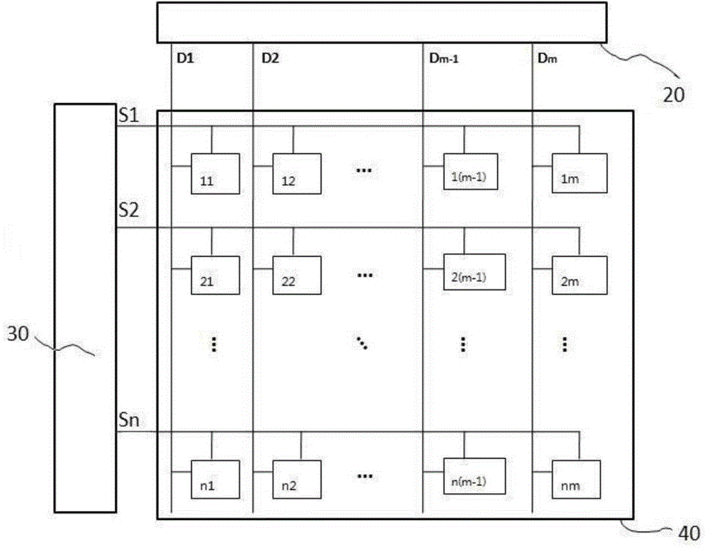
[0009] For this reason, what the present invention is to solve is the response delay existing in the existing AMOLED data drive circuit, thereby causing the problem of abnormal display, and provides a data drive circuit that can effectively improve the response characteristics of the display device and its driving method and application.

Method used


Image

  • Data driving circuit, driving method thereof, and organic light-emitting display device
  • Data driving circuit, driving method thereof, and organic light-emitting display device
  • Data driving circuit, driving method thereof, and organic light-emitting display device

Examples


Embodiment 1

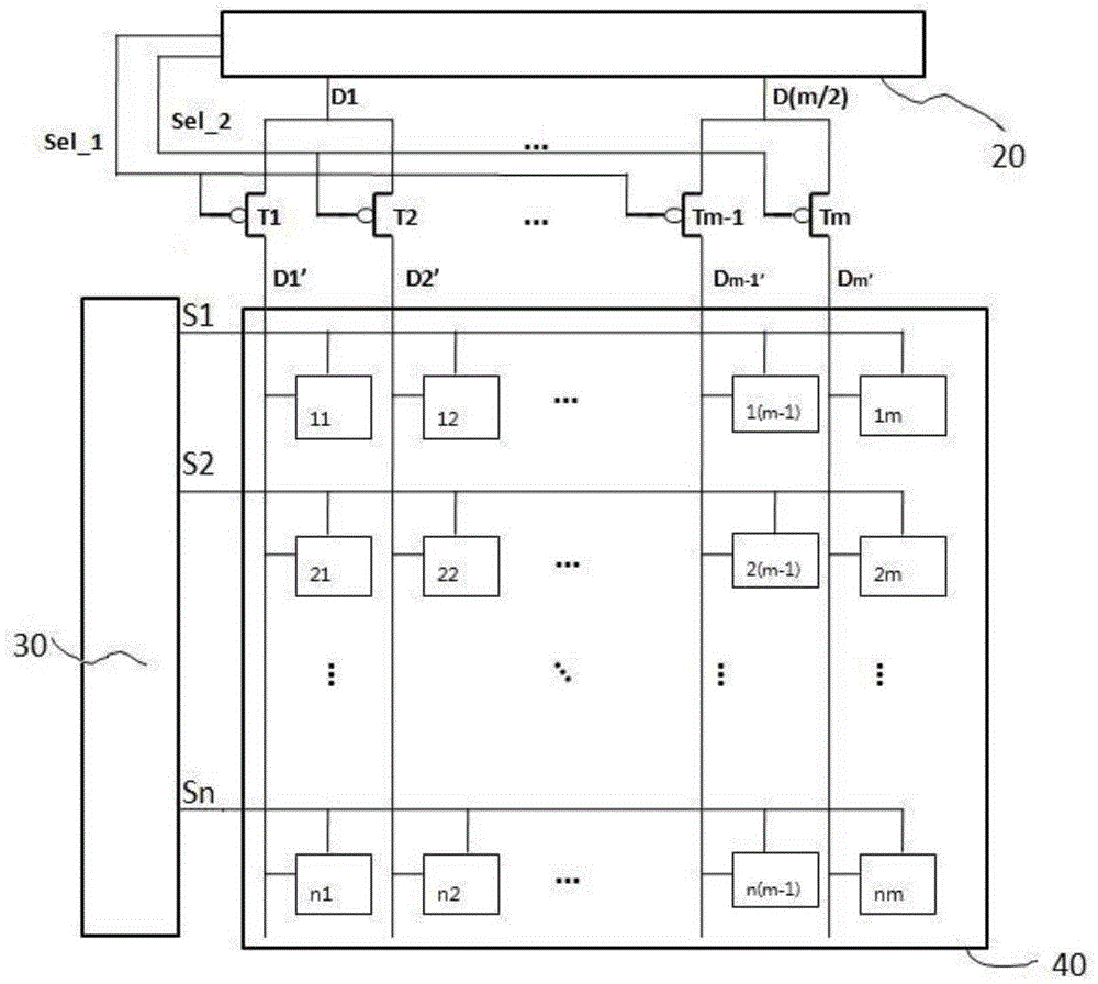
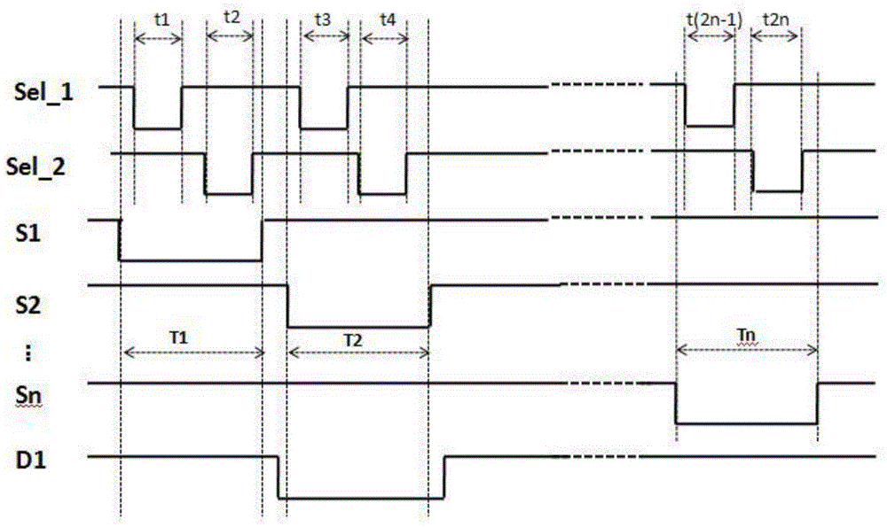
[0042] This embodiment provides a data driving circuit, such as Image 6 As shown, the data driving circuit is electrically connected to the data driver 20 through m / i column data lines D1, ... D (m / 2), and electrically connected to the scan driver 30 through n rows of scan lines S1, S2, ... Sn. In the embodiment, the value of i is 2.

[0043] The end of the first column data line D1 away from the data driver 20 is connected to the first column signal line D1' and the second column signal line D2'. Similarly, the end of the jth column data line Dj far away from the data driver 20 is connected to the 2j- 1 column signal line D2j-1' and the 2jth column signal line D2j', j=1, 2, 3, ... m / 2; the m / 2th column data line D(m / 2) is connected to one end far away from the data driver 20 There are 2 signal lines: the signal line Dm-1' of the m-1th column and the signal line Dm' of the mth column. The data drive circuit also includes pixel units 11, 12, ... 1(m-1), 1m, 21, 22 ... 2(m-1)...

Embodiment 2

[0062] This embodiment provides a data driving circuit, such as Figure 7 As shown, the specific circuit structure is the same as that of Embodiment 1, the only difference is that i is 3, that is, the end of each column of data lines away from the data driver 20 is connected with 3 columns of signal lines, the control lines are 3 rows, and the first The number of transistors is 2m / 3, and m is a non-zero natural number that is an integer multiple of 3.

[0063] Specifically, the end of the first column data line D1 away from the data driver 20 is connected to the first column signal line D1', the second column signal line D2' and the third column signal line D3'. Similarly, the jth column data line Dj The end far away from the data driver 20 is connected to the 3j-2th column signal line D3j-2', the 3j-1st column signal line D3j-1' and the 3jth column signal line D3j', j=1, 2, 3, ... m / 3; the m / 3th column data line D(m / 3) is connected to 3 signal lines at one end away from the...


PUM


Abstract

The invention provides a data driving circuit with a data signal multiplexing structure. The data driving circuit also comprises a power line for connecting a power and a second transistor connected to a power supply line. The source electrode of the second transistor is electrically connected to the power supply line. The gate of the second transistor is electrically connected to a control line in a same line. The drain electrode of the second transistor is electrically connected to different signal lines, and the connection points are between the first transistor and a display area. Through connecting a compensation power supply in the signal line, a pixel unit is initialized so as to reduce the influence of a parasitic capacitor in the pixel unit, and thus the response characteristics and display characteristics of an organic light-emitting display device with the application of the data driving circuit is effectively improved.

Description

technical field [0001] The invention relates to the field of display technology, in particular to a data driving circuit capable of effectively improving the response characteristics of a display device, a driving method thereof, and an organic light-emitting display. Background technique [0002] Flat panel display has the characteristics of complete planarization, lightness, thinness, and power saving. It is an inevitable trend and research focus of image display development. Among various types of flat-panel display devices, since the active matrix organic light-emitting display device (English full name is ActiveMatrixOrganicLightEmittingDisplay, referred to as AMOLED) uses a self-illuminating organic light-emitting diode (English full name is OrganicLightEmittingDiode, referred to as OLED) to display images, it has a short response time. Short, driven by low power consumption, and relatively better in brightness and color purity, organic light-emitting display devices h...

Claims


Application Information

Patent Timeline
Patent Type & Authority Applications(China)
IPC IPC(8): G09G3/32
CPCG09G2310/0248G09G3/3225G09G3/3275G09G2310/0297G09G2310/08G09G2320/0252G09G2230/00G09G3/3266G09G2330/02
Inventor 张小宝朱晖胡思明丁立薇黄秀颀
Owner KUNSHAN NEW FLAT PANEL DISPLAY TECH CENT
Learn More