A current protector and its manufacturing method

A technology of a current protector and a manufacturing method, which is applied to emergency protection devices, circuits, electrical components, etc., can solve the problems of large and loose cold resistance of fuses, so as to improve resistance value accuracy, reduce production and manufacturing costs, and improve safety. performance effect

Active Publication Date: 2019-03-01
NANJING SART SCI & TECH DEV
View PDF7 Cites 0 Cited by
  • Summary
  • Abstract
  • Description
  • Claims
  • Application Information

AI Technical Summary

Problems solved by technology

However, after a period of use, the product with the above-mentioned patented structure will loosen due to the weakening of the adhesion between the fuse and the end electrode under the impact of heat and cold, resulting in unfavorable phenomena such as the increase in the cold resistance of the fuse.

Method used


Image

  • A current protector and its manufacturing method
  • A current protector and its manufacturing method
  • A current protector and its manufacturing method

Examples


Embodiment 1

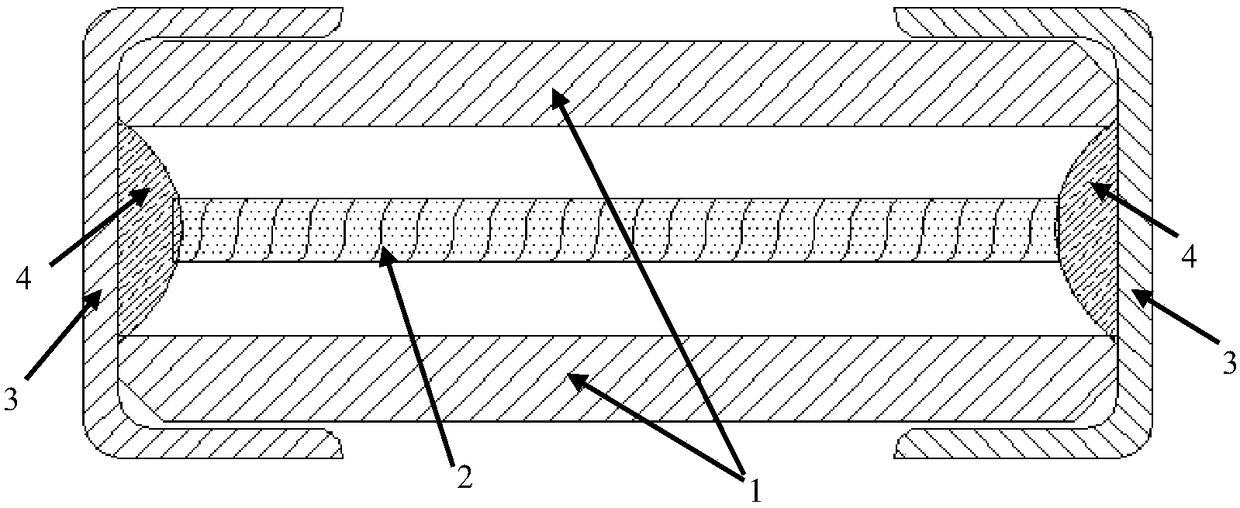
[0026] figure 1 It is a longitudinal sectional view of the ultra-sensitive protector of the present invention, the structure of which includes an insulating shell 1, a metal melt 2, left and right end caps 3 and solder 4. Wherein, the molten metal 2 is suspended in the insulating shell 1 , and the solder 4 is fixed and welded to the molten metal 2 inside the end cap 3 to form an electrical connection.

[0027] and see Figure 8 As shown, the insulating casing 1 includes three layers of PCB boards, and the three layers of PCB boards include two layers of outer PCB boards 11 and a middle PCB board 12 sandwiched between the two layers of outer PCB boards; There is a slot 13 running through the middle PCB, and the slot 13 together with the two outer PCBs 11 forms an inner hole for receiving the molten metal 2 .

[0028] The three-layer PCB boards are all FR-4 materials with a heat-resistant temperature above 260°C;

[0029] The pressing of the three-layer PCB board is to use hi...

Embodiment 2

[0031] A kind of manufacture method that is used for current protector of the present invention:

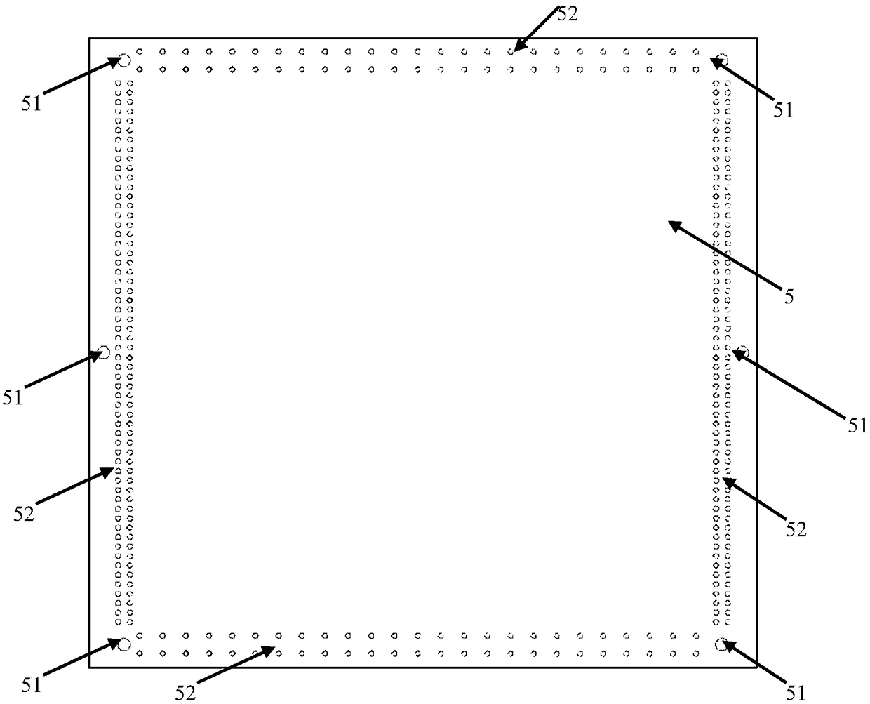
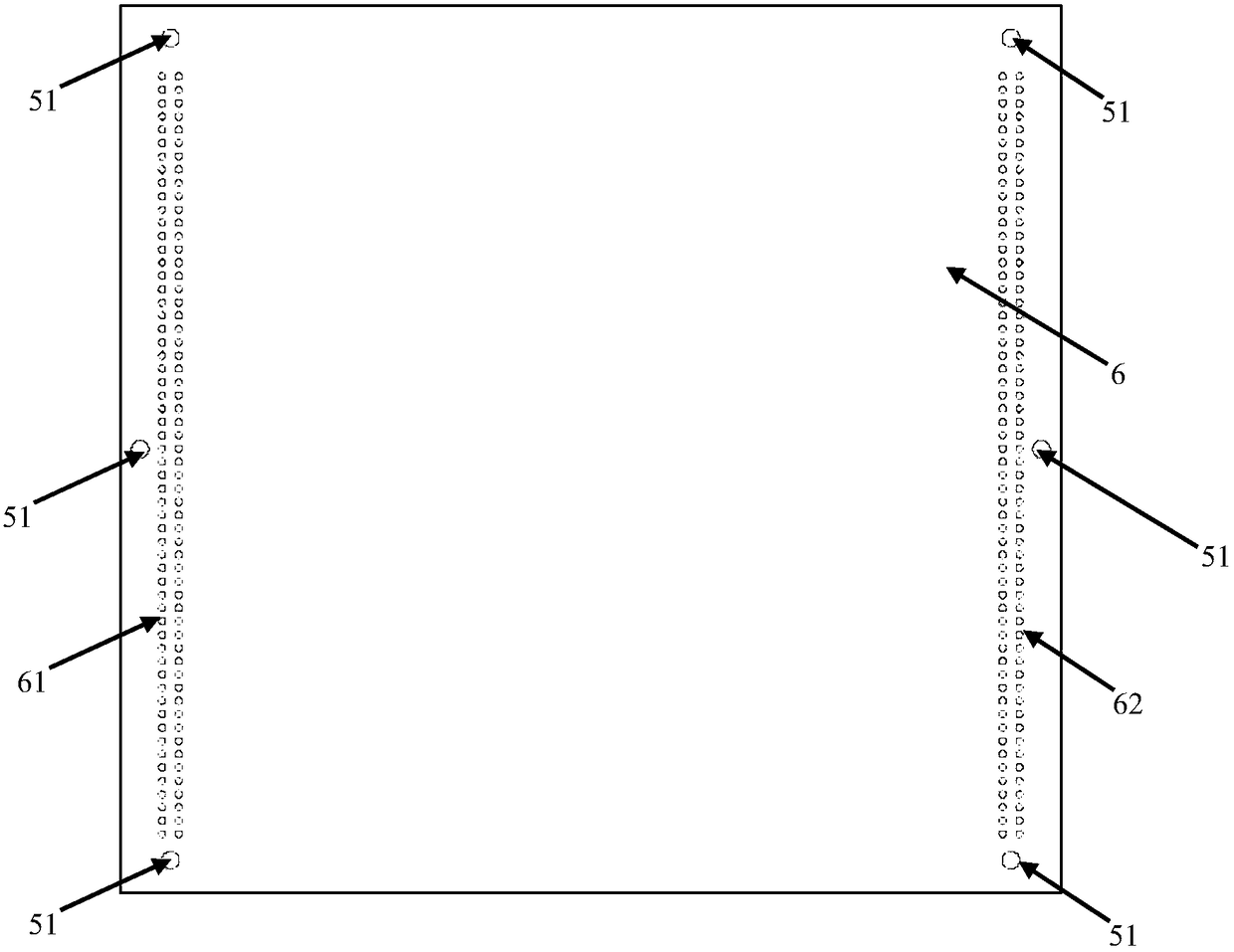
[0032] Three PCB boards are provided, including two outer PCB boards 5 and one inner PCB board 6, and each PCB board is provided with a pressing alignment hole 51 for pressing and aligning the three PCB boards;

[0033] The left side on each outer PCB board 5 is provided with at least one row of alignment holes 52 for left cutting, and the right side of each outer PCB board is provided with at least one row of alignment holes 53 for right cutting; The hole 52 is arranged symmetrically with the alignment hole 53 for right cutting; the upper side of each outer PCB board is provided with at least one row of alignment holes 54 for upper cutting, and the lower side of each outer PCB board is provided with at least one row for lower cutting. alignment holes 55 , and the alignment holes 54 for upper cutting and the alignment holes 55 for lower cutting are arranged symmetrically. The pr...

Embodiment 3

[0041] In step 1 described in Embodiment 2, due to the difference in the field of view of the PCB board cutting machine and the width of the entire PCB board, such as Figure 5 As shown, the four corners of the outer PCB board 5 and the middle positions of the sides are punched to form alignment holes 51 for product pressing, and then the alignment holes 51 for product cutting are formed by punching at certain positions of the four sides and the middle according to the product size. That is, the outer PCB 5 is further provided with a row of auxiliary cutting alignment holes 56 located in the middle of the left cutting alignment holes 52 and the right cutting alignment holes 53 . Similarly, a row of center cutting alignment holes 57 located between the upper cutting alignment holes 54 and the lower cutting alignment holes 55 is also provided. Therefore, during size cutting, the cutting alignment can refer to the alignment hole 56 for auxiliary cutting and the alignment hole 57 ...


PUM


Abstract

The invention discloses a current protector and a manufacturing method, and discloses a super-sensitive protector and a manufacturing method. A PCB tube structure is manufactured through the processes of punching, grooving, laminating, re-cutting and the like of a PCB; and a traditional ceramic tube is replaced with the PCB tube structure as a protective housing. Components of a PCB tube, an end cap, a metal melt, soldering tin and the like are combined and welded through a full-automatic protector assembly machine, so that the super-sensitive protector is obtained. On one hand, the influence on fusing characteristics of the metal melt caused by heat dissipation of the protective housing is reduced by a low heat conductivity coefficient of the PCB tube and the high dependency of fundamental characteristics of an mA-level low current product on production equipment is also reduced; and on the other hand, the bad phenomenon that the cold resistance of a fuse wire and an end surface electrode in a product employing the PCB as the housing in an existing patient abnormally increases under the hot and cold impact is effectively avoided.

Description

technical field [0001] The invention relates to a current protector, in particular to a tubular structure protector and a manufacturing method thereof. Background technique [0002] In the prior art, insulating tubes based on ceramic or glass-ceramic materials are often used as protective shells for protectors, which have many excellent properties, such as high breaking capacity, high I 2 t and anti-surge capability, low cold resistance value, etc. However, ceramic materials usually have relatively high thermal conductivity. When the rated current in the circuit is at the mA level, the protector needs to be very sensitive to cut off the circuit quickly when the current is abnormal. At this time, the protector with ceramic tube structure will be affected by the production equipment. System fluctuations will cause twice the fusing characteristics of the dispersion, and even cause twice the fusing characteristics of the fast-acting protector, resulting in potential safety haza...

Claims


Application Information

Patent Timeline
Patent Type & Authority Patents(China)
IPC IPC(8): H01H85/175H01H85/22
CPCH01H85/175H01H85/22
Inventor 南式荣杨漫雪刘明龙
Owner NANJING SART SCI & TECH DEV
Why Eureka
Try Eureka