Lead frame pin cutting structure and cutting method thereof

A cutting wire cutting, lead frame technology, applied in the direction of electrical components, electrical solid devices, circuits, etc., can solve the problems of shortened blade life, excessive blade wear, poor cutting quality, etc., to improve cutting quality, improve quality impact, The effect of prolonging the cutting life

Inactive Publication Date: 2016-07-27
WUXI CHINA RESOURCE MICRO ASSEMBLY TECH
View PDF3 Cites 2 Cited by
  • Summary
  • Abstract
  • Description
  • Claims
  • Application Information

AI Technical Summary

Problems solved by technology

like figure 1 As shown, 1' is the lead, 2' is the end of the lead, the lead frame of the traditional design QFN is adopted, the width of the lead 1' is equal to the end 2 of the lead, so the end of the lead 2 is cut and separated The metal extension and accumulation at ', the distance between the product pins 1' after cutting becomes smaller, resulting in poor cutting quality, the burr at the pin end 2' is too large, it is difficult to meet the product appearance requirements, and the blade wears too fast , which shortens the life of the blades used for cutting

Method used


Image

  • Lead frame pin cutting structure and cutting method thereof
  • Lead frame pin cutting structure and cutting method thereof
  • Lead frame pin cutting structure and cutting method thereof

Examples


Embodiment Construction

[0022] In order to make the above objects, features and advantages of the present invention more comprehensible, the present invention will be further described in detail below in conjunction with the accompanying drawings and specific embodiments.

[0023] Reference herein to "one embodiment" or "an embodiment" refers to a particular feature, structure or characteristic that can be included in at least one implementation of the present invention. "In one embodiment" appearing in different places in this specification does not all refer to the same embodiment, nor is it a separate or selective embodiment that is mutually exclusive with other embodiments.

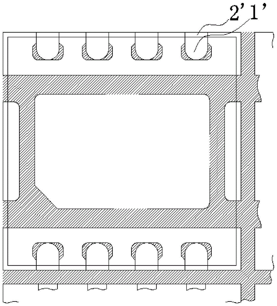
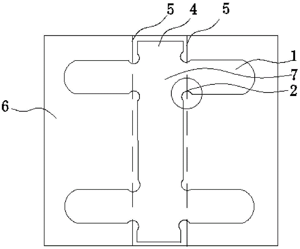
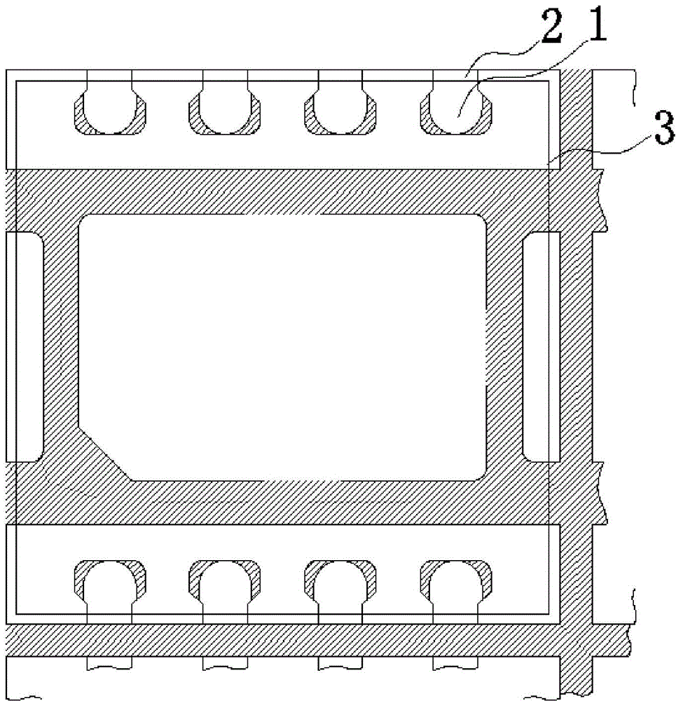
[0024] see figure 2 , figure 2 It is a structural schematic diagram of the lead frame in the present invention. Such as figure 2 As shown, the present invention provides a lead frame pin cutting structure, which is an integrated structure of metal material, and can be specifically divided into three parts: a pin connec...


PUM

PropertyMeasurementUnit
widthaaaaaaaaaa
widthaaaaaaaaaa

Abstract

The invention provides a lead frame pin cutting structure. The lead frame pin cutting structure comprises a pin connection portion, multiple pins and multiple pin end portions between the pins and the pin connection portion, wherein the quantity of the pins is equal to the quantity of the pin end portions, the pins and the pin end portions are arranged at two sides of the pin connection portion, the pins, the pin end portions and the pin connection portion are an integrated structure, and width of the pin end portions connected with the pins is smaller than width of the pins. According to the lead frame pin cutting structure, design of the pin end portions of the QFN lead frame is optimized, gaps among the pins are enhanced at an early design period, metal of a blade cutting portion is reduced, influence of a cutting stress on quality of products in a production process is ameliorated, cutting service life of a blade is prolonged, and product cutting quality is improved.

Description

【Technical field】 [0001] The invention relates to the technical field of micro-electromechanical systems, in particular to a lead frame pin cutting structure and a cutting method thereof. 【Background technique】 [0002] For quad flat no-lead package (hereinafter referred to as QFN) products that need to be cut, it is necessary to use a blade to divide the product during the cutting process, and the product can be separated after being subjected to the stress of the blade. At present, in the cutting process of QFN products, it is necessary to use a blade to separate the connected products to form individual products. During the cutting process, adjacent products begin to separate due to the rapid extrusion of the blade. see figure 1 , figure 1 It is a schematic diagram of the lead frame pin cutting structure in the prior art. Such as figure 1 As shown, 1' is the lead, 2' is the end of the lead, the lead frame of the traditional design QFN is adopted, the width of the lea...

Claims


Application Information

Patent Timeline
Patent Type & Authority Applications(China)
IPC IPC(8): H01L23/495B21F11/00
Inventor 陈莉司文全代振岁
Owner WUXI CHINA RESOURCE MICRO ASSEMBLY TECH
Why Eureka
Try Eureka