Inserted type connector

A connector and receptacle technology, which is applied in the direction of connection, parts of connecting devices, devices for connecting/disconnecting connecting parts, etc., can solve the problems of high mold forming accuracy, poor locking firmness, and high processing costs , to achieve good locking effect, better locking performance and improved firmness

Inactive Publication Date: 2016-07-27
苏州丰年科技股份有限公司
View PDF7 Cites 3 Cited by
  • Summary
  • Abstract
  • Description
  • Claims
  • Application Information

AI Technical Summary

Problems solved by technology

[0003] Usually, the plug-in connector includes a male end and a female end. After the two are plugged in, the internal rubber core is connected. In order to prevent the male and female ends from being separated when external force is applied, a lock will be added at the connection between the male and female ends. Buckle structure, and this lock structure is nothing more than the following: ① thread locking; ② steel ball locking; ③ spiral groove locking, the existing problems are that it takes up a lot of space, high processing cost and difficult to unlock, etc. Defects, not conducive to high-volume, low-cost production of connectors
[0004] In addition, usually the locking structure is only limited from one direction, axial (such as thread locking) or radial (such as steel ball locking), the locking is not firm enough, and it is easy to accidentally unlock under the influence of external force. The spiral groove locking method is more complicated in structure, and requires high precision in mold forming. It needs to use tools when unlocking, and it is inconvenient to unlock and disassemble when using in some occasions that often need to split the wiring.

Method used


Image

  • Inserted type connector
  • Inserted type connector
  • Inserted type connector

Examples


Embodiment 1

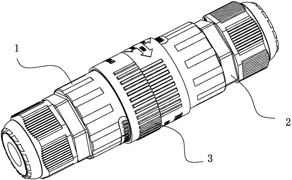
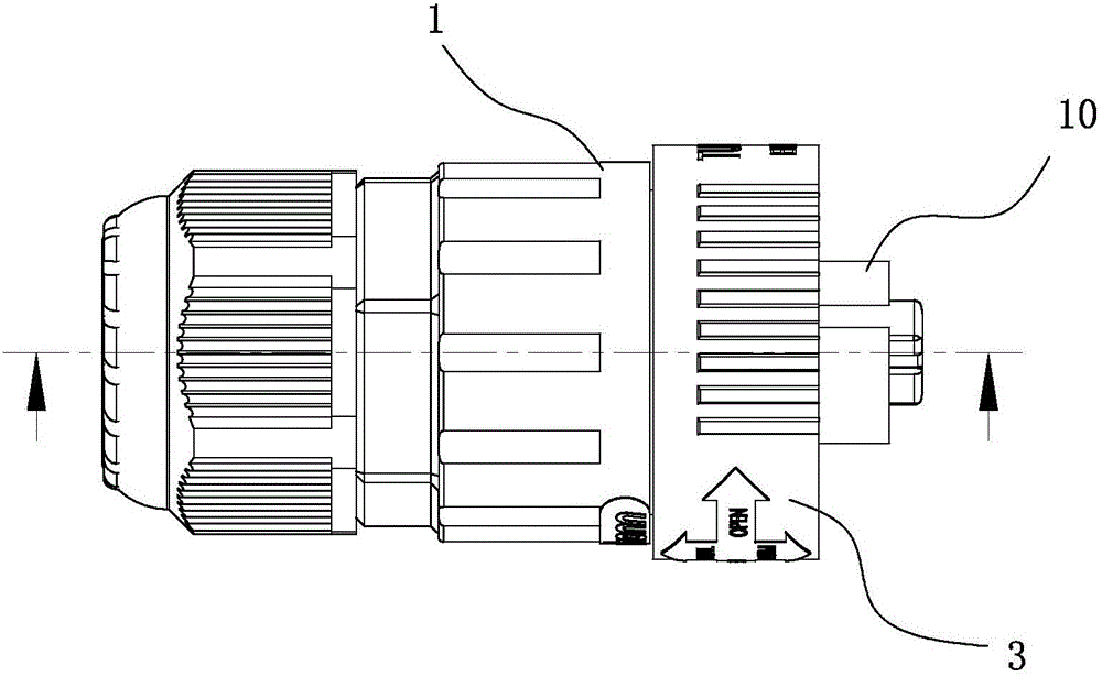
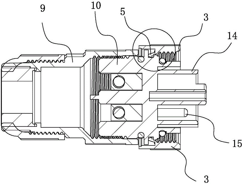
[0028] Embodiment one: see Figure 1-8 As shown, a plug-in connector includes a male end 1 and a female end 2, and a locking structure 3 set between the male end 1 and the female end 2, the locking structure 3 is in the form of a ring There are several anti-slip protrusions 4 on the outer edge surface, and a radial limit structure 5 is provided on the end surface of the inner ring wall close to one side, extending from the radial limit structure 5 to the other end surface of the inner ring wall There is a threaded structure 6 on it; the outer edge surface of the male end 1 is provided with a limit groove 7 that cooperates with the radial limit structure 5, and the outer edge surface of the female end 2 on the other side An external thread 8 engaged with the threaded structure 6 is provided on it.

[0029] Such as figure 2 , 3 As shown, the male end 1 and the female end 2 respectively include a housing 9 and a rubber core 10, the housing 9 and the rubber core 10 are screwed...

Embodiment 2

[0034] Embodiment 2: A pair of plug-in connectors, including a male end and a female end, and a locking structure set between the male end and the female end. The locking structure is ring-shaped, and the outer edge surface There are several anti-slip protrusions on the top, and a radial limit structure is provided on the end surface of the inner ring wall close to one side, and a thread structure is provided on the end surface of the other side of the inner ring wall from the radial limit structure; A limiting groove cooperating with the radial limiting structure is provided on the outer peripheral surface of the female end, and an external thread engaged with the threaded structure is provided on the outer peripheral surface of the male end on the other side.

[0035] In this embodiment, the radial limiting structure is a protruding ring arranged along the inner ring wall of the locking structure. When the protruding ring falls into the limiting groove of the female end, it ...


PUM


Abstract

The invention discloses an inserted type connector. The inserted type connector comprises a male end and a female end and is characterized by also comprising a set of locking structure, wherein the locking structure is arranged between the male end and the female end and is of an annular shape, a radial limitation structure is arranged on the end surface, near to a side, of an inner annular wall, a thread structure is arranged on the end surface extending to the other side of the inner annular wall from the radial limitation structure, a limiting groove is formed in an outer edge surface of the male end or the female end and is matched with the radial limitation structure, and an external thread engaged with the thread structure is arranged on the outer edge surface of the female end or the male end on the other side. By arranging the locking structure, bidirectional locking is achieved by matching of the radial limitation structure and the thread structure, the locking force is effectively increased, the connector is prevented from loosening due to the influence of an external force, and the connection reliability is ensured.

Description

technical field [0001] The invention relates to a connector for cables and wires, in particular to a plug-in connector. Background technique [0002] Connectors are an indispensable part of electronic equipment and an important bridge between the bus and branch lines, blocked and isolated circuits. In ensuring the continuous and reliable operation of the equipment, the primary requirement for the connector is that the connection relationship is stable and not easy to disengage; at the same time, these plugs and sockets (or male and female ends) usually need to be used for a long time, and the connector is required to be strong and durable. , Waterproof and dustproof, suitable for various outdoor harsh environments. [0003] Usually, the plug-in connector includes a male end and a female end. After the two are plugged in, the internal rubber core is connected. In order to prevent the male and female ends from being separated when external force is applied, a lock will be add...

Claims


Application Information

Patent Timeline
Patent Type & Authority Applications(China)
IPC IPC(8): H01R13/622H01R13/639
CPCH01R13/622H01R13/639
Inventor 姜伟清舒守成
Owner 苏州丰年科技股份有限公司
Why Eureka
Try Eureka