Link state detection method, device and system

A detection method and link state technology, applied in the field of communication, can solve problems such as wasting network resources

Inactive Publication Date: 2016-07-27
HUAWEI TECH CO LTD
View PDF5 Cites 12 Cited by
  • Summary
  • Abstract
  • Description
  • Claims
  • Application Information

AI Technical Summary

Problems solved by technology

[0007] The embodiment of the present invention proposes a link state detection method, device and s

Method used


Image

  • Link state detection method, device and system
  • Link state detection method, device and system
  • Link state detection method, device and system

Examples


Embodiment Construction

[0077] Embodiments of the present invention propose a link state detection method, device and system to provide a link discovery or link fault detection mechanism that can be realized without occupying too many system resources.

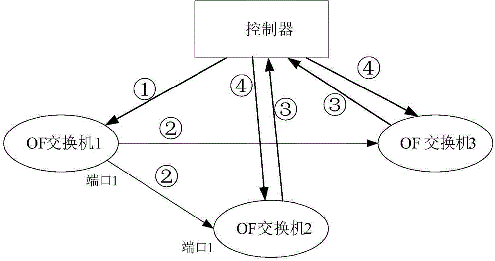
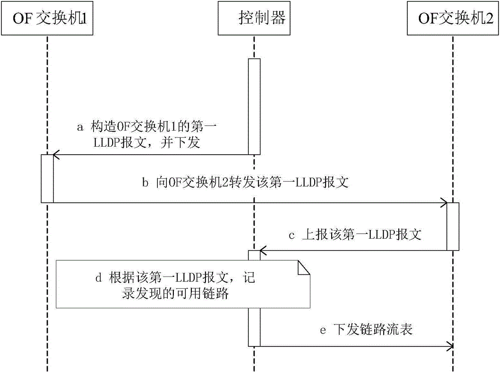
[0078] Such as figure 1As shown, it is a schematic flowchart of a link discovery method combined with a system architecture provided by an embodiment of the present invention. In the embodiment of the present invention, the OpenFlow switch is referred to as an OF switch for short. In this embodiment, the SDN network includes 3 OF switches as an example, in an actual application scenario, more OF switches may be included. Such as figure 2 As shown in , it is a schematic diagram of another flow of link discovery.

[0079] First, before the link discovery process, it is necessary to implement a general processing mechanism for LLDP packets between the controller and the switch.

[0080] S10: When the OF switch 2 is online, it will establish a conne...


PUM


Abstract

An embodiment of the invention provides a link state detection method, device and system that are applied to a software definition network SDN and used for reducing state detection messages of a link between a controller and a switch machine. After the controller discovers a usable link, the controller sends a link flow table to the switch machine, and the link flow table is used for instructing the switch machine to discarding messages, used for detecting the state of the usable link, forwarded by other switch machines via the usable link.

Description

technical field [0001] Embodiments of the present invention relate to communication technologies, in particular to a link state detection method, device and system. Background technique [0002] The architecture of a software-defined network (Software Defined Networking, SDN) includes a controller and a switch, and the controller is the core of the SDN network. The application configures and operates various settings and behaviors of the switch through the controller, so as to achieve the purpose of controlling the switch to realize various application logics; similarly, the switch also feeds back various information of the data plane to the application through the controller, so that the application can out the corresponding control logic. The OpenFlow protocol is used to describe the standard of information used for the interaction between the controller and the switch, as well as the interface standard of the controller and the switch. The core part of the protocol is a...

Claims


Application Information

Patent Timeline
IPC IPC(8): H04L12/26H04L12/823H04L47/32
CPCY02D30/00
Inventor 朱旭琪
Owner HUAWEI TECH CO LTD
Why Eureka
Try Eureka